
Treball Final de Grau - UBdiposit.ub.edu/dspace/bitstream/2445/132808/1... · final quinoline after...
80
Treball Final de Grau Tutor Dr. Jose Maria Gutiérrez González Departament d’Enginyeria Química i Química Analítica Design of a batch plant for quinoline derivatives manufacture Josep Sastre Galmés January 2019
Transcript of Treball Final de Grau - UBdiposit.ub.edu/dspace/bitstream/2445/132808/1... · final quinoline after...
Treball Final de Grau
Tutor
Dr. Jose Maria Gutiérrez González Departament d’Enginyeria Química i
Química Analítica
Design of a batch plant for quinoline derivatives manufacture
Josep Sastre Galmés January 2019


Aquesta obra està subjecta a la llicència de: Reconeixement–NoComercial-SenseObraDerivada
http://creativecommons.org/licenses/by-nc-nd/3.0/es/


If you are going through hell, keep going.
Winston Churchill
Agrair al Dr. Jose Maria Gutiérrez pel seguiment del projecte i la disposició per ajudar.
Gràcies, com no podria ser, a la meva família per donar-me l’oportunitat d’estudiar i pel suport
durant tota la vida. Als amics, per ser-hi quan es necessiten.
Per últim, gràcies als Enginyers de futur per amenitzar l’estància a la península i per facilitar
l’aprenentatge durant aquests anys.

CONTENTS
SUMMARY i
RESUM iii
1. INTRODUCTION 1
1.1. QUINOLINE 1
1.1.1. Properties and uses 2
1.1.2. Synthesis 3
1.2. BATCH PLANTS 5
2. OBJECTIVES 9
3. PROCESS SELECTION 13
4. PRELIMINARY PROCESS DESIGN 23
5. FINAL PROCESS DESIGN AND PRODUCTION SCHEDULING 35
6. CONCLUSIONS 45
REFERENCES AND NOTES 49
ACRONYMS 51
APPENDICES 53
APPENDIX 1: QUINOLINE DERIVATIVES MANUFACTURE PATENTS 55

Design of a batch plant for quinoline derivatives manufacture i
SUMMARY
Quinoline is a heterocyclic compound with derivatives having a wide range of applications in
the pharmaceutical industry. Traditionally, quinolines have been synthesized from anilines. Batch
plants are used due to their flexibility in the production of different chemicals. Moreover, demand
of the market does not justify the need of a continuous supply of quinolines, so it will be produced
in batches to control which quinoline derivative is needed.
The main objective of this project is to design a batch plant to produce various quinoline
derivatives departing from a laboratory recipe to synthesize a single derivative. Design has been
done based on one derivative, but others could be introduced thanks to the flexibility of both
quinoline and process. Quinoline traditional synthesis are similar, departing from a simple aniline.
Manufacture process from the patents are flexible because more than one derivative can be
produced from a similar reaction path.
A study on quinoline derivatives manufacture patents has been conducted to find a suitable
process that can be scaled up. Once an appropriate recipe has been found, it has been introduced
in Aspen Batch Process Developer® and brought from laboratory to an industrial scale. In order
to get to this industrial scale, quinoline derivative production has been raised from 29 g to 70 kg
and new equipment units of the process have been selected analysing their size utilization and
occupancy time.
To implement campaign schedule, total amount of quinoline derivative has been fixed to 2000
kg. Batch number and its size have been studied to find the combination with a shorter total time.
Optimal campaign has been found to be 21 batches of 97.32 kg to produce 2000 kg of
quinoline derivative in 22.5 days.
Keywords: Batch process, quinoline, scheduling, Aspen

Design of a batch plant for quinoline derivatives manufacture iii
RESUM
La quinolina és un compost heterocíclic amb derivats que tenen varies aplicacions a l’àmbit
de la indústria farmacèutica. Tradicionalment, aquests derivats s’han sintetitzat a partir d’anilines.
S’utilitzaran plantes en discontinu degut a la seva flexibilitat per produir diferents substàncies. A
més, la demanda de mercat no justifica la necessitat de tenir un subministrament continu d’un
cert derivat, per tant es durà a terme a una planta amb lots per a poder controlar quin compost
es necessita.
L’objectiu principal és dissenyar una planta en discontinu per a la producció de diferent
derivats de la quinolina a partir d’una recepta de laboratori. El disseny s’ha fet a partir d’un derivat
concret, però es podria ampliar a diversos degut a la flexibilitat de la síntesis de la quinolina i la
del propi procés. Les síntesis tradicionals de quinolines utilitzen anilines com a reactant comú, i
en el cas del propi procés seleccionat, es podrien produir diverses quinolines amb unes reaccions
similars.
S’han estudiat les patents de la producció de quinolines per trobar una recepta base pel
projecte que es pugui escalar. Una vegada ha estat escollit, s’ha introduït a l’Aspen Batch Process
Developer® per escalar el procés d’escala laboratori fins a industrial. Per arribar a aquesta nova
escala, la producció del derivat de la quinolina ha augmentat de 29 g a 70 kg. Els equips s’han
canviat tenint en compte paràmetres com el percentatge de volum utilitzat i el temps total
d’utilització.
Per implementar el calendari de la campanya, s’ha fixat la producció total del derivat de la
quinolina a 2000 kg, trobant el número de lots i els kilograms per lot que redueixen el temps total.
La combinació òptima s’ha trobat a 21 lots de 97.32 kg per produir 2000 kg del derivat de la
quinolina en 22.5 dies.
Paraules clau: Processos en discontinu, quinolina, scheduling, Aspen


Design of a batch plant for quinoline derivatives manufacture 1
1. INTRODUCTION
Quinolines are important substances due to their pharmaceutical applications. Synthesis of
different quinolines are sometimes similar, so it can be possible to design a plant to manufacture
various quinoline compounds.
Manufacture of quinoline derivatives are optimally made in a batch plant because
pharmaceutical industry requires less production and more flexibility than other industrial areas.
Given the objective of this work, the design of a batch plant for the manufacture of quinolines,
in this chapter, the main characteristics of the quinolines are described, in a first section, and, in
a second section, the main peculiarities of batch plants are introduced in order to take them into
account in the design of the manufacturing process for quinolines
QUINOLINE
1.1.1. Chemical definition
Quinoline is a heterocyclic aromatic organic compound with the chemical formula C9H7N and
a molecular weight of 129.16 g/mol. Quinoline is the preferred IUPAC name but it can also be
named 1-Benzopyridine or 1-Azanaphtalene. It has the following structural formula:
Figure 1. Molecular structure of quinoline

2 Sastre Galmés, Josep
It is a colourless hygroscopic liquid with a characteristic odour that turns brown on exposure
to light. This substance has a density of 1.095 kg/m3, with a boiling point of 238ºC and melting
point of -15ºC at atmospheric pressure. (1)
Quinoline is soluble in hot water and most organic compounds. Due to this solubility in water,
it has a significant potential for mobility in the environment, which could result into water
contamination. A way to avoid this contamination would be degradating quinoline with certain fit
microorganisms such as Rhodococcus species, isolated from soil and paper mill sludge. (2)
Short term inhalation of quinoline vapours irritates the eyes, nose, and throat and might cause
headaches, dizziness and nausea. It is moderately toxic by skin contact. Quinoline can be found
in alcoholic beverages, various plants from Mentha species and in crude oil within the virgin diesel
fraction. Nevertheless, its fraction is insignificant.
It was first extracted from coal tar (by-product of the production of coke and coal gas from
coal) by Friedlieb Ferdinand Runge in 1834. (3)
1.1.2. Properties and uses
Basic quinoline does not have any remarkable direct application, it is mainly used to produce
its derivatives, that will be called just quinolines along this project.
Quinolines have a wide range of biological and pharmacological activity.(4) Principal
application of these derivatives has found to be in the treatment of solid tumours, especially
quinoline-3-carboxylic acid derivatives and amido-anilinoquinolines. (5)
Bisquinolines, compounds with two quinoline groups, possess a degree of antimalarial
activity against both chloroquine-resistant and chloroquine-sensitive parasites. Other quinoline
compounds have also been found to be successful in malaria treatment. (6)
4-substituted-7-trifluoromethylquinolines have a good analgesic activity related to their nitric
oxide releasing properties.(7) 2-(Furan-2-yl)-4-phenoxy-quinoline derivatives are inhibitors of
lysozyme and β-glucuronidase release, working as anti-inflammatory. (8)
Phenoxy substituted quinolines have been synthesized with a fair amount of anti-bacterial
activity.(9) 7-chloro-quinoline derivatives have been found to be effective against multi-drug
resistant tuberculosis. (10)
Design of a batch plant for quinoline derivatives manufacture 3
Certain tetrahydroquinolines present antifungal activities, especially against Candida
albicans and Fusarium oxysporum.(11) Anilidoquinoline derivatives have activity against
encephalitis virus (12) and desfluoroquinolines are used in HIV treatment.(13)
2,4-arylquinolines are used against nematode Haemonchus contortus, a parasitic worm. It
maintains its activity in strains of H. contortus resistant to other treatments such as levamisole,
ivermectin or thiabendazole. (14)
Aside from its applications in the pharmacological industry, one quinoline derivative is used
as a dye. Quinoline Yellow (Sodium 2(1,3-dioxoindan-2-yl)quinolinedisulfonate)(15) is a greenish
yellow additive designated in Europe as E104. It is usually added to food such as juices or sorbets
and in cosmetics, principally hair products and perfume. This colorant is banned for certain uses
in the United States because it is believed to have caused dermatitis in some cases. (16)
1.1.3. Synthesis
As it was said before, quinoline was first extracted from coal tar, the principal líquid product
resulting from the carbonization of coal. However, due to their low fraction it will have to be
produced synthetically.
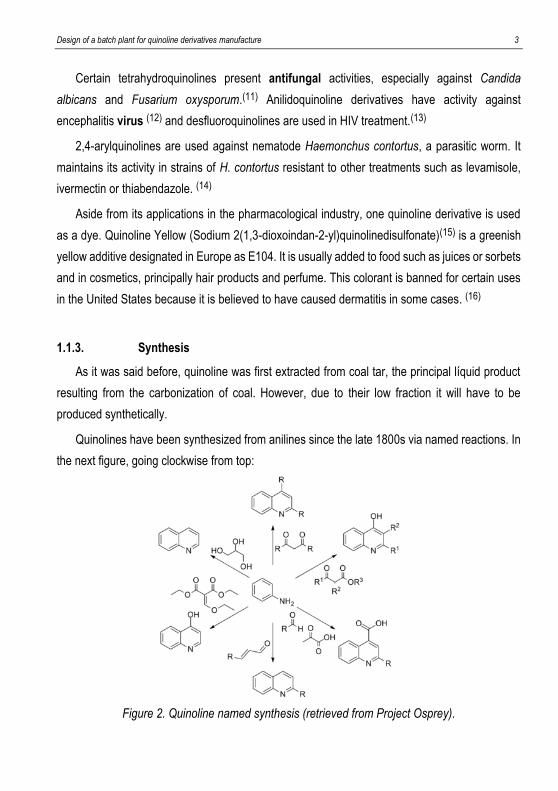
Quinolines have been synthesized from anilines since the late 1800s via named reactions. In
the next figure, going clockwise from top:
Figure 2. Quinoline named synthesis (retrieved from Project Osprey).
4 Sastre Galmés, Josep
- Combes synthesis, condensation of unsubstituted anilines with β-diketones, forming the
final quinoline after an acid-catalyzed ring closure of an intermediate.
- Conrad-Limpach synthesis, is similar to Combes synthesis, but condensating anilines
with β-ketoesters to synthesize 4-hydroxyquinolines.
- Doebner reaction, which reacts an aniline with an aldehyde and pyruvic acid to form
quinoline-4-carboxylic acids.
- Doebner-Miller reaction, where quinoline derivatives are obtained from α,β-unsaturated
carbonyl compounds catalyzed by Lewis acids such as tin tetrachloride.
- Gould-Jacobs reaction is a series of reactions started with the subtitution of an aniline
with ethyl ethoxymethylenemalonate.
- Skraup synthesis, which heats aniline with glycerol and nitrobenzene in presence of
sulfuric acid.
As it can be seen, these different quinolines can be synthesized departing from a simple
anilines. This flexibility is useful for a plant to manufacture different quinolines, because there
would be a common reactant.
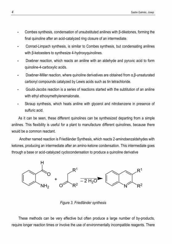
Another named reaction is Friedländer Synthesis, which reacts 2-aminobenzaldehydes with
ketones, producing an intermediate after an amino-ketone condensation. This intermediate goes
through a base or acid-catalyzed cyclocondensation to produce a quinoline derivative
Figure 3. Friedländer synthesis
These methods can be very effective but often produce a large number of by-products,
require longer reaction times or involve the use of environmentally incompatible reagents. There
Design of a batch plant for quinoline derivatives manufacture 5
are other methods using alternative reaction media such as supercritical fluids, ionic liquids,
polyethylene glycol or solvent-free methods. However, even if these reactions are chemically
possible they would be hard to reproduce in an industrial scale. There has also been some
microwave-assisted and ultrasound-promoted experiments done from that named reactions with
the same problems. For example, 6-hydroxyquinoline has been synthesized from glycerol via
improved microwave-assisted modified Skraup reaction. (17)
Other synthesis have been studied in organic chemistry, but they are pretty specific, with low
yield and purity so bringing them to industrial scale would not be that useful. (18)
Nevertheless, certain quinolines may be synthesized with its own reaction path without using
anilines. For example, they can be manufactured using simpler quinolines or from a totally
different compound. This is the case if only patented production is looked at. Currently, none of
these synthesis have been published in an industrial scale, but they are definitely done due to its
pharmaceutical activity.
1.2. BATCH PLANTS
Like nearly all pharmaceutical products, manufacture of quinoline derivatives will be a batch
process due to the low amount but high purity of the product needed. Batch process produce a
fixed amount of product (batch), repeated over again and again with new feedstock until target
total amount is reached.
Batch plants have a lower initial capital investment than continuous and more flexibility in both
production process and scale. Specifically, in this project more than one substance could be
produced depending on market request, which is unpredictable. It is practical to produce
quinolines in a batch plant due to its flexibility, with various compound synthesis sharing tasks to
be carried out.
Batch process are often defined in a recipe style or process step procedure, a list of
physicochemical operations (tasks) including their duration, generally developed at laboratory
scale.

6 Sastre Galmés, Josep
When a basic route or recipe at laboratory scale is selected, the process at industrial scale can
be developed and designed by scaling up starting from laboratory scale to a larger kilo lab, to a
pilot plant and eventually into industrial manufacturing.
Batch process design implicates the assigning of process tasks to the available equipment or
equipment to be designed. In order to optimize the production, it is required to know the
occupancy time of an equipment, the time that tasks taking place in this equipment needs to be
completed. The sum of the occupancy times of all the equipment needed for the process is the
batch time, the time needed for producing a batch since first task is started until last task is
finished.
A campaign is defined as the sum of batches to produce a certain amount of a product in a
concrete time. Campaign time would be the time that it takes to produce all this fixed amount the
product, from the first batch until the last one.
Batch plants can be operated in overlapping or non-overlapping mode. In overlapping mode, a
new batch is started when occupancy time of each equipment permits it, although the previous
batch has not yet finished. Non-overlapping mode would mean that a batch would not be loaded
until the previous one has ended.
Overlapping mode is usually used, given that if several batches are processed simultaneously
the idle time of the equipment, the time that each equipment remains unoccupied, is reduced.
Using overlapping mode, process cycle time is defined by maximum occupancy time of all
equipment units in a process. The equipment unit with maximum occupancy time is the time-
limiting one, representing a bottleneck given that another batch cannot be processed until this
equipment has not been emptied from the previous one. The cycle time defines the number of
batches that can be produced by time unit.
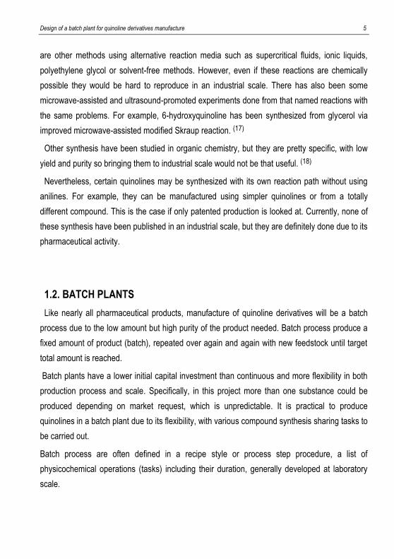
Schedule is usually represented in a Gantt chart, where operation times for every equipment are
shown. It is useful to visualize together the various times discussed: batch time, cycle time and
campaign time.
Both overlapped and non-overlapped Gantt charts will be shown beneath, but as it was told earlier
only the overlapped campaign will be studied in the final chosen process.
Design of a batch plant for quinoline derivatives manufacture 7
.
Figure 4. Gantt chart comparation
As it can be visualized, using overlapping mode idle time is minimized, translating into a higher
production. In this example, Unit 3 would be the one defining cycle time, batches would have to
be calculated so that second batch enters this unit right when the first one exits.
The volume of the different equipment units limits the amount to be processed in each unit, and
the volume of one equipment unit would limit the batch size. It would be the equipment which
capacity utilization is 100% because does not fit a greater batch, representing a volume
bottleneck.
Other resources limiting the production capacity may be workforce, availability of raw material
and utilities and size of storage tanks.
All in all, it seems that campaign optimization is done analysing both cycle time and capacity
utilization, but this analysis should not be done separately because they are dependent variables.
When increasing batch size, cycle time and operating times might also be increased. For complex
processes there are mathematical algorithms including not only discussed parameters (batch
size, available equipments…) but others such as materials of vessels and maximum operating
temperature. (19)

8 Sastre Galmés, Josep

Design of a batch plant for quinoline derivatives manufacture 9
2. OBJECTIVES

10 Sastre Galmés, Josep

Design of a batch plant for quinoline derivatives manufacture 11
2. OBJECTIVES
As stated in the introduction, quinoline compounds have plenty of uses in the pharmaceutical
industry. Some of them have a similar synthesis, therefore manufacture of various derivatives
could be done in one single plant.
The main objective of this project is to design a batch plant for the manufacture of different
quinolines derivatives scheduling production depending on market demand.
Design will be firstly made on a particular quinoline, which then could be changed to include
others. To achieve this goal, the following tasks will be proceeded:
- Selection of a recipe through a study of quinoline manufacture patents, a research on
quinoline recipes will be conducted in order to select the most suitable.
- Design the process using Aspen Batch Process Developer®: Once the recipe is
chosen, it will be incorporated in the simulation software and scaled to industrial scale.
Selection of equipment units will be carried out from available equipment in Aspen®
catalogue.
- Defining scheduling of the plant, minimizing campaign time for a determined production.
Occupation times will be checked in case they can be lowered.

12 Sastre Galmés, Josep

Design of a batch plant for quinoline derivatives manufacture 13
3. PROCESS SELECTION

14 Sastre Galmés, Josep
Design of a batch plant for quinoline derivatives manufacture 15
3. PROCESS SELECTION
Synthesis of quinolines have been studied in the organic chemistry field over the last decades
due to their pharmaceutical properties. However, only a few of them have been turned into an
accepted patent with a recipe. Moreover, there is not available information about industrial
manufacture of quinoline derivatives. A study on quinoline derivatives manufacture patents will
be conducted to find a suitable recipe to start the process.
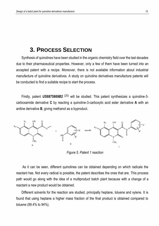
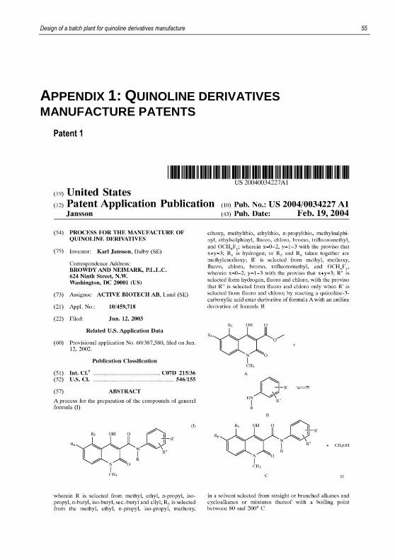
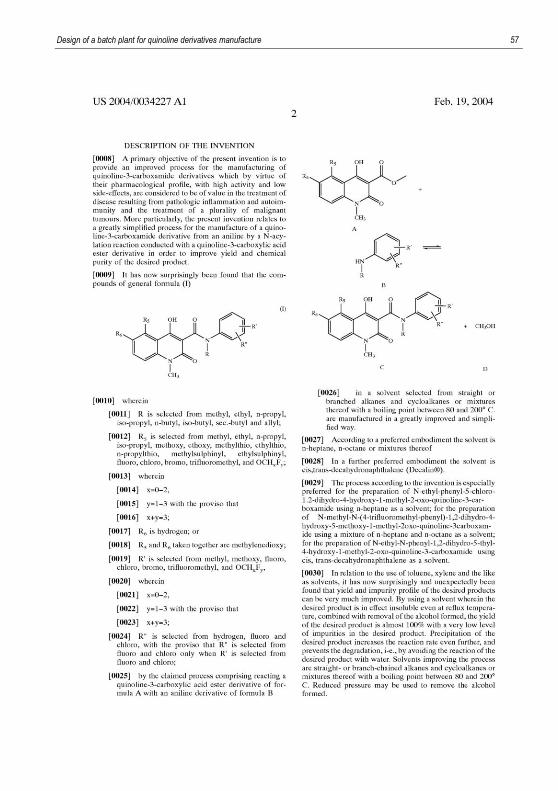
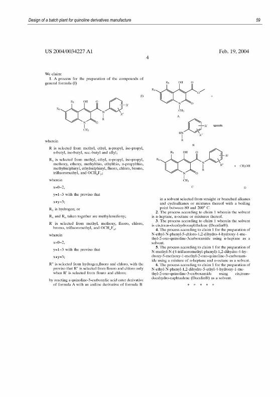
Firstly, patent US6875869B2 (20) will be studied. This patent synthesizes a quinoline-3-
carboxamide derivative C by reacting a quinoline-3-carboxylic acid ester derivative A with an
aniline derivative B, giving methanol as a byproduct.
Figure 5. Patent 1 reaction
As it can be seen, different quinolines can be obtained depending on which radicals the
reactant has. Not every radical is possible, the patent describes the ones that are. This process
path would go along with the idea of a multiproduct batch plant because with a change of a
reactant a new product would be obtained.
Different solvents for the reaction are studied, principally heptane, toluene and xylene. It is
found that using heptane a higher mass fraction of the final product is obtained compared to
toluene (99.4% to 94%).

16 Sastre Galmés, Josep
The patent also points out the synthesis of a concrete quinoline-3-carboxylic ester derivative
(1,2-Dihydro-4-hydroxy-6-chloro-1-methyl-2-oxo quinoline-3-carboxylic acid methyl ester), which
then could be reacted with an aniline to create the final product of the patent.
This synthesis can be studied because it is a complete recipe that could be scaled. Incomplete
recipes that do not point out every mass of product or reaction time could not be scaled that
clearly, for example reaction time would have to be estimated and kinetics of these reactions have
not been widely studied.
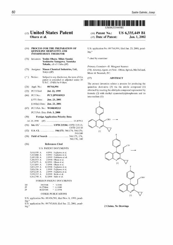
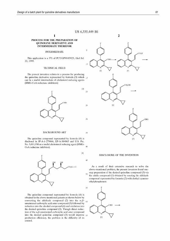
Second researched patent is US6335449B1 (21), which synthesizes a different quinoline (3) via
the nitrile compound (1), obtained reacting the aldehyde compound (2) with diethyl
cyanomethylphosphonate.
Figure 6. Patent 2 reaction
The product of this patent is used as an intermediate of cholesterol reducing agents.
Essentially, inhibiting the rate-controlling enzyme (HMG-CoA reductase or statin) of the
mevalonate pathway, a metabolic pathway that produces cholesterol. Drugs with a lipid-lowering
activity are usually just called statins due to this enzyme, including a wide amount currently
available in the market.

Design of a batch plant for quinoline derivatives manufacture 17
Compound (3) has been synthesized by converting aldehyde compound (2) into a α,β-
unsaturated carboxylic acid, reducing it into an alcohol compound and oxidating to the desired
product. Direct reduction of the α,β-unsaturated carboxylic acid is possible, improving production
efficiency but reducing control of the process. Therefore, this patent arises as an answer to a
better process to manufacture this final product.
It gives a recipe to synthesize both the nitrile compound (1) and the final product through a series
of physicochemical transformations, so it could also be designed in Aspen Batch Process
Developer®.
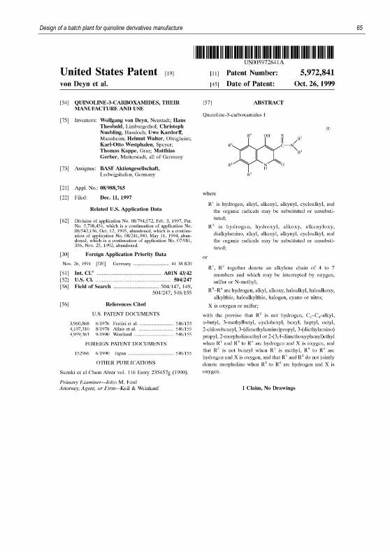
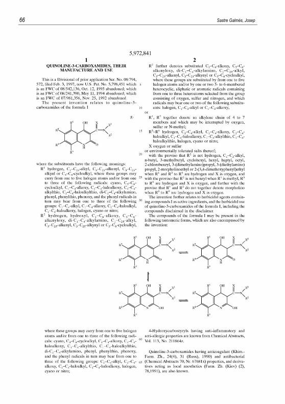
Third studied patent, US5972841A (22), produces quinoline-3-carboxamides reacting quinoline-3-
carboxylate with a substituted amine.
Figure 7. Patent 3 reaction
Like the first invention, various quinolines could be manufactured with this patent. Every possible
radical of the reactants are described in the patent. This reaction is optimal in the 100-180ºC
range, with an inert organic solvent such as benzene, toluene, various ethers and alcohols or a
mixture of these substances. Atmospheric pressure in usually used but depending on the amine
it may be advantageous to carry out the reaction in a higher pressure with an autoclave.
It is claimed that two of that compounds, applied postemergence at a rate of 3 kg/ha have a high
herbicidal action.
Recipes given are just for the manufacture of quinoline-carboxamides departing from quinoline-
carboxylates, with insufficient physicochemical transformations to carry out a lengthy thesis.
18 Sastre Galmés, Josep
With the right radicals, this third patent (quinoline-3-carboxamide derivative) actually uses the
same primary reactant as the first patent (quinoline-3-carboxylic acid derivative) but reacting it
with a substituted amine instead of an aniline derivative.
Comparing all these patents, the first and the third one would allow a production of a variety of
quinolines but the second just one. As explained before, the goal of this project is to design a
batch plant to manufacture different quinoline derivatives, so these two processes could serve a
base to produce some of them. However, the third patent does not contain a recipe to synthesize
the quinoline-3-carboxamide, so it would not be possible to scale
Furthermore, the first patent is made by Active Biotech®, a biotechnological company that
already uses these quinoline-3-carboxamide derivatives in experimental drugs such as
Tasquinomod®, investigated for the treatment of solid tumors, especially prostate cancer.
Laquinomod® is also a quinoline-3-carboxamide used as an oral treatment for multiple sclerosis.
The second patent is exploited by Nissan Chemical®, who have been commercializing
Pitavastatin®. Basically, it is a derivative of the final product of that patent with the same function,
lowering cholesterol production.
The third one, made by BASF, is said to have some herbicide activity. Nevertheless, it has not
been translated into a real application. Moreover, from all the combination of radicals, only two of
them have that mentioned herbicidal action.
Except these three patents, there has not been a lot of information about quinoline production, as
it was said most of the literature is about the chemical possibility to synthetize very specific
quinoline derivatives with certain conditions that would not be easy to replicate in an industrial
level.
All in all, it seems the first patent could be more useful for the purpose of a multiproduct plant
thanks to its flexibility to produce various quinolines and its already quantifiable utilization as a
pharmaceutical drug.
Design of a batch plant for quinoline derivatives manufacture 19
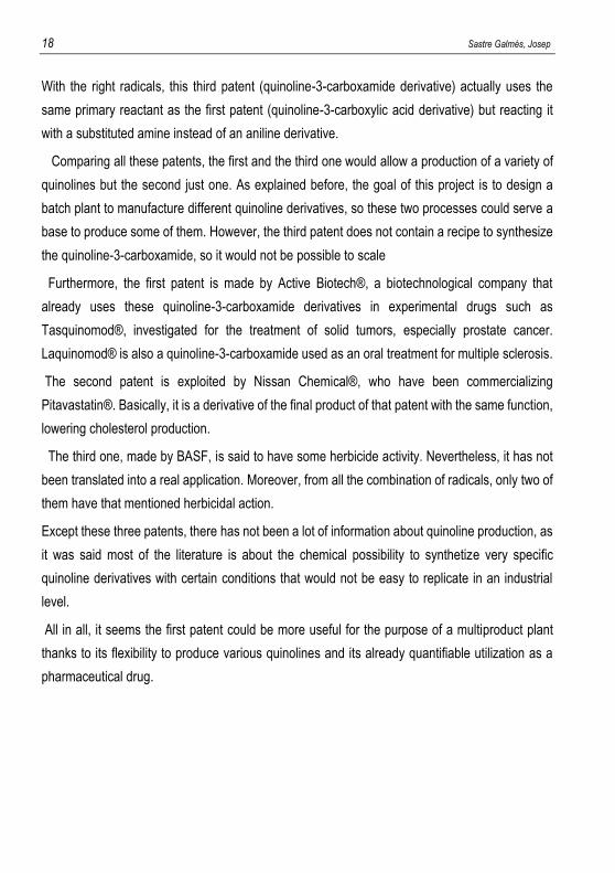
In order to visualize and compare these experimental drugs with the first patent, chemical
structure of Tasquinimod® is shown below:
Figure 8. Molecular structure of Tasquinimod®
Being a quinoline-3-carboxylic acid derivative, it could be produced from the first recipe using
reactants with the needed radicals. As explained before, patent US6875869B2 contains the recipe
for the production of a certain quinoline 3-carboxylic ester derivative (1,2-Dihydro-4-hydroxy-6-
chloro-1-methyl-2-oxo quinoline-3-carboxylic acid methyl ester)
The recipe, extracted from Example 1 of the discussed patent, will be copied beneath:
“2-Amino-6-chlorobenzoic acid (30 g) was suspended in 1,4-dioxane (225 ml) and ethyl
chloroformate (75 ml) was added. The mixture was heated at reflux for 1 hour, then cooled back
to 50ºC and acetyl chloride (75 ml) was added. The mixture was stirred for 10 hours, after which
the precipitated product was filtered off and washed with toluene. Drying yields 6-chloroisatoic
anhydride (33 g, 97% yield). 6-chloroisatoic anhydride (30 gram) was dissolved in
dimethylacetamide (300 ml) and cooled to 5ºC over a nitrogen atmosphere. Sodium hydride (5.8
g, 70%) was added portionwise, followed by addition of methyl iodide (11.5 ml). The reaction
mixture was stirred at room temperature for 18 hours. Sodium hydride (5.8 g, 70%) was added
followed by addition of dimethyl malonate (20 ml) and the mixture was heated to 85ºC. After 3
hours at 85ºC, the mixture was cooled and diluted with cold water (2.4 litre). The product was
precipitated by addition of HCl (aq.) until pH=1.5-2. Filtration of the precipitated product and
recrystallisation from methanol gave the title compound (29g, 70% yield).”
Reaction path is not described in the patent, but it has been predicted from the substances added
in the process. Also, the patent points out that 5-chloroisatoic anhydride is produced, but it has
20 Sastre Galmés, Josep
been verified that chemically 6-chloroisatoic anhydride must be produced, synthesis of 5-
chloroisatoic is not possible from these reactants.
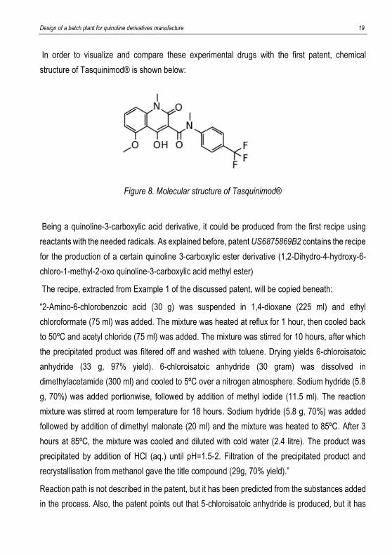
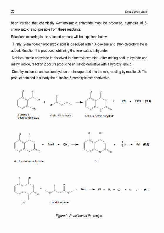
Reactions occurring in the selected process will be explained below:
Firstly, 2-amino-6-chlorobenzoic acid is dissolved with 1,4-dioxane and ethyl-chloroformate is
added. Reaction 1 is produced, obtaining 6-chloro isatoic anhydride.
6-chloro isatoic anhydride is dissolved in dimethylacetamide, after adding sodium hydride and
methyl iodide, reaction 2 occurs producing an isatoic derivative with a hydroxyl group.
Dimethyl malonate and sodium hydride are incorporated into the mix, reacting by reaction 3. The
product obtained is already the quinoline 3-carboxylic ester derivative.
Figure 9. Reactions of the recipe.
Design of a batch plant for quinoline derivatives manufacture 21
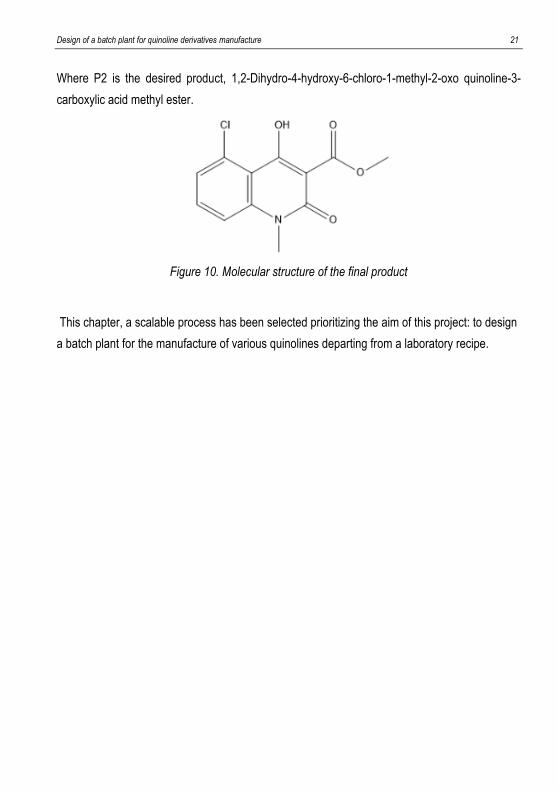
Where P2 is the desired product, 1,2-Dihydro-4-hydroxy-6-chloro-1-methyl-2-oxo quinoline-3-
carboxylic acid methyl ester.
Figure 10. Molecular structure of the final product
This chapter, a scalable process has been selected prioritizing the aim of this project: to design
a batch plant for the manufacture of various quinolines departing from a laboratory recipe.

22 Sastre Galmés, Josep

Design of a batch plant for quinoline derivatives manufacture 23
4. PRELIMINARY PROCESS DESIGN

24 Sastre Galmés, Josep
Design of a batch plant for quinoline derivatives manufacture 25
4. PRELIMINARY PROCESS DESIGN
The aim of this first process design is to scale the recipe from laboratory to industrial scale,
choosing new equipment bearing in mind their
Recipe of the patent will be introduced in Aspen Batch Process Developer®, where different
discontinuous tasks can be introduced with certain parameters. For example, “React” task
demands reaction time and selecting the desired pre-introduced reaction, but other parameters
can be introduced if needed.
If task time is not known, predetermined time is used but it will be approximated when
production scale is obtained. For example, charging and filtering predetermined time used by
Aspen® is 15 min.
The recipe is obviously in a laboratory scale, so laboratory equipment such as 500ml Erlenmeyer
Flask, 250ml Filter Flask or 5L Tank are used. It can be divided into production of 6-chloroisotoic
anhydride, production of the quinoline carboxylic ester derivative and its purification.
Eventually, when recipe is scaled, other appropriate equipment will be selected. The whole
recipe already introduced in Aspen Batch Process Developer® is shown beneath:
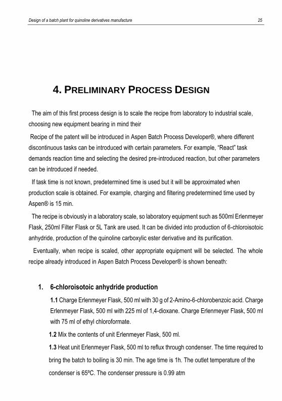
1. 6-chloroisotoic anhydride production
1.1 Charge Erlenmeyer Flask, 500 ml with 30 g of 2-Amino-6-chlorobenzoic acid. Charge
Erlenmeyer Flask, 500 ml with 225 ml of 1,4-dioxane. Charge Erlenmeyer Flask, 500 ml
with 75 ml of ethyl chloroformate.
1.2 Mix the contents of unit Erlenmeyer Flask, 500 ml.
1.3 Heat unit Erlenmeyer Flask, 500 ml to reflux through condenser. The time required to
bring the batch to boiling is 30 min. The age time is 1h. The outlet temperature of the
condenser is 65ºC. The condenser pressure is 0.99 atm

26 Sastre Galmés, Josep
1.4 Cool unit Erlenmeyer Flask, 500 ml to 50ºC
1.5 Mix the contents of unit Erlenmeyer Flask, 500 ml. React in unit Erlenmeyer Flask
500 ml via R1. Reaction occurs over 10 h.
1.6 Filter the batch from unit Erlenmeyer Flask, 500 ml in Filter Flask, 250 ml.
1.7 Dry the batch in unit Filter Flask, 250 ml.
1.8 Transfer contents of unit Filter Flask, 250 ml to Erlenmeyer Flask, 1000 ml. Transfer
89% of vessel contents
2. Quinoline ester production
2.1 Charge Erlenmeyer Flask, 1000 ml with 300 ml of dimethylacetamide.
2.2 Cool unit Erlenmeyer Flask, 1000 ml to 5ºC
2.3 Charge Erlenmeyer Flask, 1000 ml with 5.8 g of sodium hydride and 11.5 ml of
methyl iodide
2.4 Heat Erlenmeyer Flask, 1000 ml to 23ºC
2.5 React in unit Erlenmeyer Flask, 1000 ml via R2. Reaction occurs over 18 h.
2.6 Charge Erlenmeyer Flask, 1000 ml with 5.8 g of sodium hydride and 25 ml of
dimethyl malonate.
2.7 Heat unit Erlenmeyer Flask, 1000 ml to 85ºC.
2.8 React in unit Erlenmeyer Flask, 1000 ml via R3. Reaction occurs over 3 h.
2.9 Transfer contents of unit Erlenmeyer Flask, 1000 ml to Lab Tank, 5 L.
2.10 Charge Lab Tank, 5L with 2.4 L of water. Maintain the temperature at 10ºC
2.11 Adjust pH in unit Lab Tank, 5L. The final pH is 1.7.
2.12 Crystallize the batch in unit Lab Tank.
2.13 Filter the batch from unit Lab Tank, 5 L in Filter Flask, 125 ml.
2.14 Transfer contents of unit Filter Flask, 125 ml to Erlenmeyer Flask 1000 ml.
2.15 Charge Erlenmeyer Flask, 1000 ml with 800 ml of methanol.
2.16 Dissolve all solids in Erlenmeyer Flask, 1000 ml.
Design of a batch plant for quinoline derivatives manufacture 27
2.17 Transfer contents of unit Erlenmeyer Flask, 1000 ml to Crystallizing Dish.
2.18 Crystallize the batch in unit Crystallizing Dish.
2.19 Filter the batch from unit Crystallizing Dish in unit Filter Flask, 125 ml.
Using this recipe, 29 g of 1,2-Dihydro-4-hydroxy-6-chloro-1-methyl-2-oxo quinoline-3-
carboxylic acid methyl ester are obtained, with a 70% yield. Before the first crystallization,
approximately 300 ml of HCl (aq.) 0.1M are added to get a pH value of 1.7. Hydrochloric acid
concentration will be increased in the last scale in order to reduce the amount of acid needed to
get to that value.
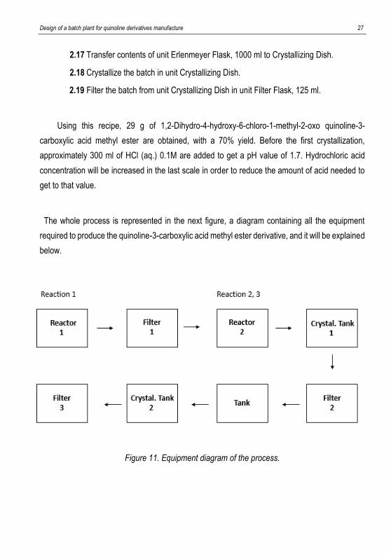
The whole process is represented in the next figure, a diagram containing all the equipment
required to produce the quinoline-3-carboxylic acid methyl ester derivative, and it will be explained
below.
Figure 11. Equipment diagram of the process.

28 Sastre Galmés, Josep
Reactor 1 is where reactants of the first reaction (2-amino-6-chlorobenzoic acid and ethyl
chloroformate), its solvents (1,4-dioxane) and the reaction itself occurs. Filter 1 separates the
desired product of the first reaction, 6-chloro isatoic anhydride, from excess reactant, the solvent
used, and the other products (hydrogen chloride and ethanol).
This filtered product is transferred to Reactor 2, where it will be mixed with dimethylacetamide
(solvent) and the other reactants of the second reaction (sodium hydride and methyl iodide) to
carry the second reaction out. The third reaction also occurs in Reactor 2, so its respective
reactants (sodium hydride and dimethyl malonate) are added.
When the third reaction is completed, contents of Reactor 2 are transferred to the crystallizing-
filtering cycle, where the final product (1,2-Dihydro-4-hydroxy-6-chloro-1-methyl-2-oxo quinoline-
3-carboxylic acid methyl ester) is purified. Patent does not specify how many equipment is used
in the crystallizing-filtering cycle, so it was initially thought to have two tanks between last two
filters. One of them (Tank) is basically just to add methanol, which could just be added directly to
Crystallization Tank 2. Nevertheless, actual scale up simulation would not be affected if this Tank
is initially considered and then taken off, because both tanks will always have the same volume.
Once the laboratory recipe is introduced in Aspen Batch Process Developer®, the process is
scaled up to a bigger amount of product. First of all, scale-up is actually non-linear: when a
process is increased in size, surface area to mass proportion changes. Because of this, some
properties of the system change in a non-linear way. Among others, reaction kinetics,
thermodynamics, fluid dynamics or agitation. However, a rigorous computational fluids dynamics
analysis would be a completely different project, so scale-up will be assumed to be an equal
increase in every chemical substance to then analyse the optimal equipment for the selected
amount of product.
In this case, production of quinoline derivative is increased from 29 g to 70 kg per batch. This
number is an arbitrary amount, just to have the process in a greater scale, close to the final
manufacture. It could have been scaled up first to a smaller amount, but this way, with a quantity
similar to manufacture scale, task times such as heating or cooling of the reactor and
crystallization will be able to be considered constant.
Process has been scaled from the production of quinoline-3 ester derivative, but it could be done
from any other substance or even applying a common scale factor in all the equipment.
Design of a batch plant for quinoline derivatives manufacture 29
The problem of applying the same scale factor to all equipment is that not every equipment
volume can be obtained. Most equipment producers can build personalized mechanical device at
an increased cost, but in this project only traditional capacities from their catalogue will be used.
Because of this, scale will be done from the final product.
In order to optimize the cost of the equipment, size utilization among Aspen equipment
catalogue will be looked at, aiming for an 85-90%. Higher size utilization is not recommended,
and lower would mean that a great part of the volume of the equipment is wasted. Nevertheless,
in some cases an optimal equipment is not found so a lower size utilization will have to be used.
Aspen catalogue consists of basic equipment without brand and others with brands. Basic
equipment is going to be used, but in case properties of any equipment are needed, equipment
of the producers will be appealed. For example, reactor V201, with 1000 L of maximum capacity
is used. If parameters such as heating area are needed, data sheets of De Dietrich or Pfaulder
1000 L reactors will be checked. This data will be important to approximate heating or cooling
time of the reactor.
Last filter, which separates the final product (P2) and methanol has not been taken into
account, but it will be considered in the last simulation involving campaign.
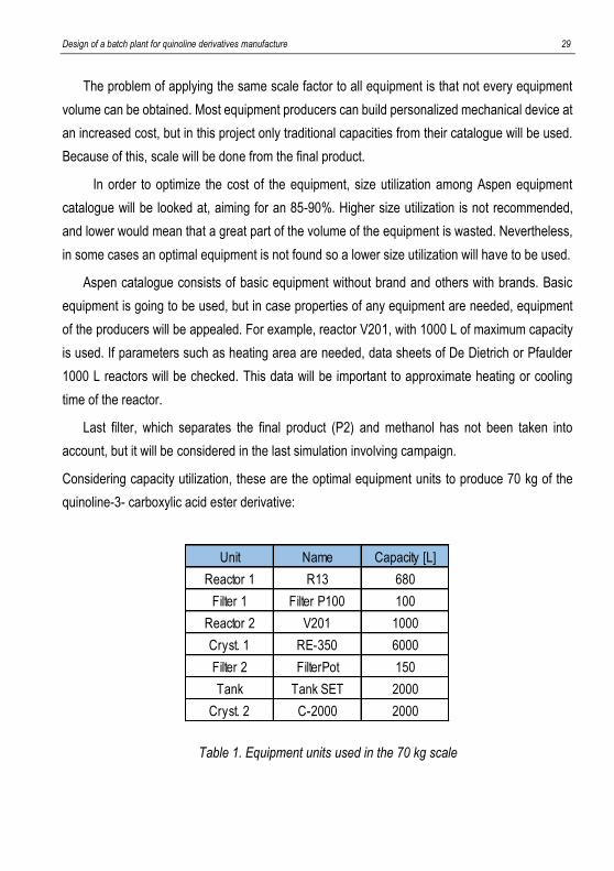
Considering capacity utilization, these are the optimal equipment units to produce 70 kg of the
quinoline-3- carboxylic acid ester derivative:
Table 1. Equipment units used in the 70 kg scale
Unit Name Capacity [L]
Reactor 1 R13 680
Filter 1 Filter P100 100
Reactor 2 V201 1000
Cryst. 1 RE-350 6000
Filter 2 FilterPot 150
Tank Tank SET 2000
Cryst. 2 C-2000 2000
30 Sastre Galmés, Josep
Volume of R13 may seem unnatural if it is taken from a catalogue, but that capacity is actually
150 imperial or UK galloons. Using these reactors does not have any problem itself, but it would
be cheaper to bring them from nearer, supposing these producers are based in the UK. Anyway,
all equipment will have standard volumes when manufacture scale is obtained.
Capacity of RE-350 might look excessive compared the other volumes, but it makes sense
because of all the water and HCl that are added to proceed to the first crystallization.
As it was said, Tank SET and C-2000 will definitely have an equal volume because they are
carrying the same. Tasks of Tank SET are just the addition of methanol and its respective
transferring from the previous to the next equipment unit, so if this tank is taken off once the
manufacture scale is obtained, global time would not change that much. The next equipment units
would not be affected in any way.
Occupancy time is the time a task is taking place in the equipment, basically the sum of task
times. It is not constant along the scaling-up process because of transferring and filtering tasks,
which will be considered constant because there is not that much change between 70 kg and final
scalation. “Fixed” tasks, such as reactions or crystallization will be considered constant because,
like it was said before, it is not possible to obtain enough kinetical and thermodynamic data.
Heating or cooling time of the jacketed reactor would also change because heating area of the
heat exchanger varies with volume, but all of these variables will be considered later on, when
manufacture scale is studied.
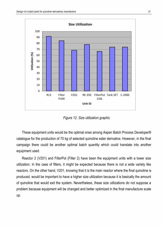
In the next graph size utilization for a production of 70 kg of 1,2-Dihydro-4-hydroxy-6-chloro-
1-methyl-2-oxo quinoline-3-carboxylic acid methyl ester is shown:
Design of a batch plant for quinoline derivatives manufacture 31
Figure 12. Size utilization graphic
These equipment units would be the optimal ones among Aspen Batch Process Developer®
catalogue for the production of 70 kg of selected quinoline ester derivative. However, in the final
campaign there could be another optimal batch quantity which could translate into another
equipment used.
Reactor 2 (V201) and FilterPot (Filter 2) have been the equipment units with a lower size
utilization. In the case of filters, it might be expected because there is not a wide variety like
reactors. On the other hand, V201, knowing that it is the main reactor where the final quinoline is
produced, would be important to have a higher size utilization because it is basically the amount
of quinoline that would exit the system. Nevertheless, these size utilizations do not suppose a
problem because equipment will be changed and better optimized in the final manufacture scale
up.
0
10
20
30
40
50
60
70
80
90
100
R13 FilterP100
V201 RE-350 FilterPot150L
Tank SET C-2000
Uti
lizat
ion
(%
)
Unit ID
Size Utilization
32 Sastre Galmés, Josep
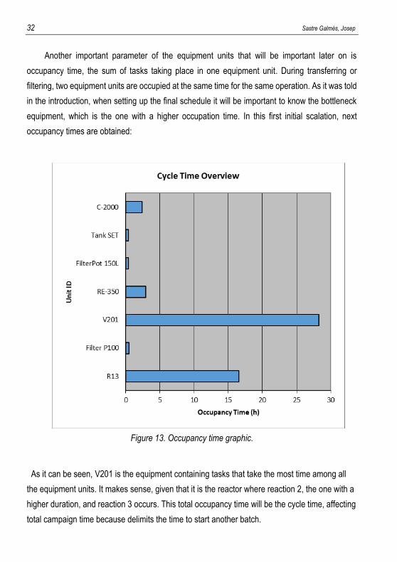
Another important parameter of the equipment units that will be important later on is
occupancy time, the sum of tasks taking place in one equipment unit. During transferring or
filtering, two equipment units are occupied at the same time for the same operation. As it was told
in the introduction, when setting up the final schedule it will be important to know the bottleneck
equipment, which is the one with a higher occupation time. In this first initial scalation, next
occupancy times are obtained:
Figure 13. Occupancy time graphic.
As it can be seen, V201 is the equipment containing tasks that take the most time among all
the equipment units. It makes sense, given that it is the reactor where reaction 2, the one with a
higher duration, and reaction 3 occurs. This total occupancy time will be the cycle time, affecting
total campaign time because delimits the time to start another batch.
Design of a batch plant for quinoline derivatives manufacture 33
Like it was explained, these occupancy times are not actually constant along the scaling up
because when increasing the volume of the batch, transferring and filtering time should change.
Moreover, different equipment means new heat transfer area, with a different cooling or heating
time. Still, in this graphic, none of these task times have been approximated. This occupancy
times could be described as basic times taken from the patent, with Aspen® filling unknown
times with a predetermined time. Nevertheless, this predetermined time is not a random number
but their general approximation for a certain task. In the next chapter these times will be
approximated using available data.
Even if some of that tasks are not constant, the task that takes more time (reaction) will be
considered constant, so at the end batch time will always be similar.
Essentially, this analysis to find suitable equipment to produce 70 kg of 1,2-Dihydro-4-hydroxy-
6-chloro-1-methyl-2-oxo quinoline-3-carboxylic acid methyl ester has been done by trying to
have the highest size utilization possible among all the equipment units.

34 Sastre Galmés, Josep
Design of a batch plant for quinoline derivatives manufacture 35
5. FINAL PROCESS DESIGN AND PRODUCTION
SCHEDULING

36 Sastre Galmés, Josep
Design of a batch plant for quinoline derivatives manufacture 37
5. FINAL PROCESS DESIGN AND PRODUCTION
SCHEDULING
Before starting with production schedule, it is important to check the occupation time of every
equipment. When the laboratory recipe was introduced in Aspen Batch Process Developer®, if
any task time was not known predetermined time was used. Essentially, every task time was
known except charge, heating/cooling and crystallization.
New charge times were approximated using average industrial pumping flow in case of liquid
substances, and solids were thought to be an operator inserting them directly to the equipment
from an industrial sack. Predetermined time of charge task was 15 min in every case, so it has
been changed.
Heating or cooling time of the jacketed reactor was calculated using the design equation of
the heat exchanger and calculating heat transfer rate via mass flow rate of the fluid, heat capacity
and temperature change. The heat capacity of the contents of the reactor and the overall heat
transfer of the heat exchanger cannot be found, but its value can be approximated. Heating area
of the jacketed reactor can be found on the catalogue of De Dietrich reactors, where other data
such as main dimensions on nozzles on vessel can be retrieved. (23)
At the end, these actualized occupancy times should not change that much, because most of
them are from reaction times, which will be considered constant when changing equipment. As it
was said, scale-up is actually non-linear because of reaction kinetics, thermodynamics and fluid
dynamics but these conditions cannot be quantified easily so in this project reaction times will be
maintained at the recipe times.
New occupancy times, calculated as it has been discussed, are shown below:
38 Sastre Galmés, Josep
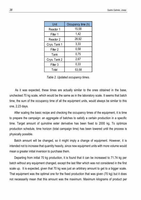
Table 2. Updated occupancy times.
As it was expected, these times are actually similar to the ones obtained in the base,
unchecked 70 kg scale, which would be the same as in the laboratory scale. It seems that batch
time, the sum of the occupancy time of all the equipment units, would always be similar to this
one, 2.23 days.
After scaling the basic recipe and checking the occupancy times of the equipment, it is time
to prepare the campaign: an aggregate of batches to satisfy a certain production in a specific
time. Target amount of quinoline ester derivative has been fixed to 2000 kg. To optimize
production schedule, time horizon (total campaign time) has been lowered until the process is
physically possible.
Batch amount will be changed, so it might imply a change of equipment. However, it is
intended not to increase that quantity heavily, since new equipment units with more volume would
mean a greater initial inversion to purchase them.
Departing from initial 70 kg production, it is found that it can be increased to 71.74 kg per
batch without any equipment changed, except the last filter which was not considered in the first
scale up. It is expected, given that 70 kg was just an arbitrary amount to get to a bigger scale.
That equipment was the optimal one for the fixed production that was given (70 kg) but it does
not necessarily mean that this amount was the maximum. Maximum kilograms of product per
Unit Occupancy time (h)
Reactor 1 15,58
Filter 1 1,42
Reactor 2 28,92
Crys. Tank 1 3,33
Filter 2 0,58
Tank 0,75
Crys. Tank 2 2,67
Filter 3 0,33
Total 53,58
Design of a batch plant for quinoline derivatives manufacture 39
batch for a combination of equipment is reached when any of these equipment units has a 100%
size utilization.
This 71.74 kg production is the base case, which will be optimized using the optimization tool of
Aspen Batch Process Developer®
.
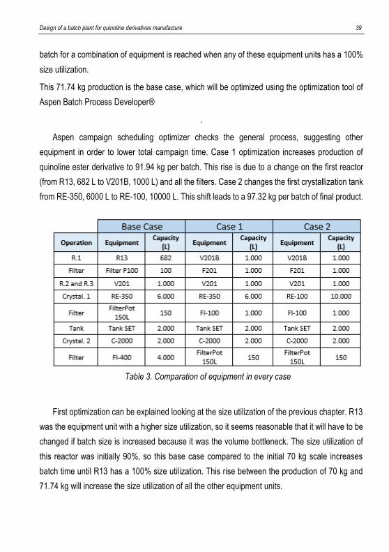
Aspen campaign scheduling optimizer checks the general process, suggesting other
equipment in order to lower total campaign time. Case 1 optimization increases production of
quinoline ester derivative to 91.94 kg per batch. This rise is due to a change on the first reactor
(from R13, 682 L to V201B, 1000 L) and all the filters. Case 2 changes the first crystallization tank
from RE-350, 6000 L to RE-100, 10000 L. This shift leads to a 97.32 kg per batch of final product.
Table 3. Comparation of equipment in every case
First optimization can be explained looking at the size utilization of the previous chapter. R13
was the equipment unit with a higher size utilization, so it seems reasonable that it will have to be
changed if batch size is increased because it was the volume bottleneck. The size utilization of
this reactor was initially 90%, so this base case compared to the initial 70 kg scale increases
batch time until R13 has a 100% size utilization. This rise between the production of 70 kg and
71.74 kg will increase the size utilization of all the other equipment units.
40 Sastre Galmés, Josep
FI-400 was the last filter added, knowing that the global process would be optimized, the
volume was highly overestimated just in case. This volume decrease was already expected.
That increase in the first and the second filter capacities can be explained due to the poor
catalogue of filters found in Aspen. After the 150 L filter, the next one is this 1000 L filter used. If
this project had to be turned into a real plant, new filters between 150 and 1000 L would have to
be designed or searched at the corresponding catalogue from the producer.
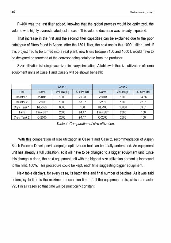
Size utilization is being maximized in every simulation. A table with the size utilization of some
equipment units of Case 1 and Case 2 will be shown beneath:
Table 4. Comparation of size utilization.
With this comparation of size utilization in Case 1 and Case 2, recommendation of Aspen
Batch Process Developer® campaign optimization tool can be totally understood. An equipment
unit has already a full utilization, so it will have to be changed to a bigger equipment unit. Once
this change is done, the next equipment unit with the highest size utilization percent is increased
to the limit, 100%. This procedure could be kept, each time suggesting bigger equipment.
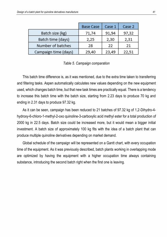
Next table displays, for every case, its batch time and final number of batches. As it was said
before, cycle time is the maximum occupation time of all the equipment units, which is reactor
V201 in all cases so that time will be practically constant.
Unit Name Volume [L] % Size Util. Name Volume [L] % Size Util.
Reactor 1 V201B 1000 79.98 V201B 1000 84.66
Reactor 2 V201 1000 87.67 V201 1000 92.81
Crys. Tank 1 RE-350 6000 100 RE-100 10000 63.51
Tank Tank SET 2000 94.47 Tank SET 2000 100
Crys. Tank 2 C-2000 2000 94.47 C-2000 2000 100
Case 1 Case 2
Design of a batch plant for quinoline derivatives manufacture 41
Table 5. Campaign comparation
This batch time difference is, as it was mentioned, due to the extra time taken to transferring
and filtering tasks. Aspen automatically calculates new values depending on the new equipment
used, which changes batch time, but that new task times are practically equal. There is a tendency
to increase this batch time with the batch size, starting from 2.23 days to produce 70 kg and
ending in 2.31 days to produce 97.32 kg.
As it can be seen, campaign has been reduced to 21 batches of 97.32 kg of 1,2-Dihydro-4-
hydroxy-6-chloro-1-methyl-2-oxo quinoline-3-carboxylic acid methyl ester for a total production of
2000 kg in 22.5 days. Batch size could be increased more, but it would mean a bigger initial
investment. A batch size of approximately 100 kg fits with the idea of a batch plant that can
produce multiple quinoline derivatives depending on market demand.
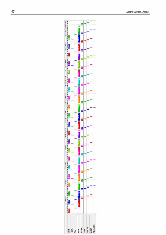
Global schedule of the campaign will be represented on a Gantt chart, with every occupation
time of the equipment. As it was previously described, batch plants working in overlapping mode
are optimized by having the equipment with a higher occupation time always containing
substance, introducing the second batch right when the first one is leaving.
42 Sastre Galmés, Josep
Design of a batch plant for quinoline derivatives manufacture 43
In this graphic, every batch is designed with one colour, with every sum of task times (occupation
time) for every equipment unit.
What was mentioned about the highest occupation time of an equipment unit, which would be the
cycle time can be visualized in this graphic. Obviously, Reactor 2 (V201c), where the second and
third reactions take place, will be the equipment unit with a higher sum of task times taking place
inside.
Comparing different batches, time difference between the same task will always be cycle time,
because it is the optimal schedule for a campaign of a batch plant operating in overlapping mode.
First four batches are shown in this schedule chart, but global schedule would go until 21 batches
are produced. HE-04c, which has not been mentioned in all the project, is the condenser used to
heat reactor V201B. It has not been designed, but it appears in Aspen Batch Process Developer®
generated Gantt chart and the optimal one from Aspen equipment list have been chosen.
Emphasizing what was explained last chapter, Tank SETc could be deleted because basically
was just added to charge methanol, which could be loaded into the crystallizer C-2000c. General
simulation would not be changed remarkably, because these charging and mixing task times are
insignificant compared to reacting times.
Once that an optimal campaign schedule for a single quinoline derivative has been obtained, the
main objective can be considered. A multiproduct batch plant can be implemented in two ways.
On the one hand, a single product campaign, where all batches of one derivative are
manufactured before switching to another. On the other hand, with a mixed product campaign,
were batches of various quinolines are produced following a certain sequence.
The use of a certain mode will depend on which derivatives the pharmaceutical industry
demands, so production schedule of this multiproduct batch plant will be variable and uncertain.

44 Sastre Galmés, Josep

Design of a batch plant for quinoline derivatives manufacture 45
6. CONCLUSIONS

Design of a batch plant for quinoline derivatives manufacture 47
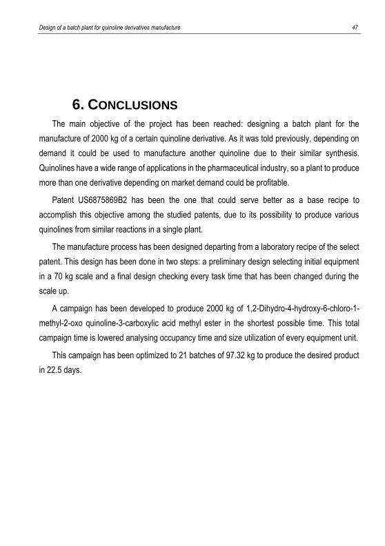
6. CONCLUSIONS
The main objective of the project has been reached: designing a batch plant for the
manufacture of 2000 kg of a certain quinoline derivative. As it was told previously, depending on
demand it could be used to manufacture another quinoline due to their similar synthesis.
Quinolines have a wide range of applications in the pharmaceutical industry, so a plant to produce
more than one derivative depending on market demand could be profitable.
Patent US6875869B2 has been the one that could serve better as a base recipe to
accomplish this objective among the studied patents, due to its possibility to produce various
quinolines from similar reactions in a single plant.
The manufacture process has been designed departing from a laboratory recipe of the select
patent. This design has been done in two steps: a preliminary design selecting initial equipment
in a 70 kg scale and a final design checking every task time that has been changed during the
scale up.
A campaign has been developed to produce 2000 kg of 1,2-Dihydro-4-hydroxy-6-chloro-1-
methyl-2-oxo quinoline-3-carboxylic acid methyl ester in the shortest possible time. This total
campaign time is lowered analysing occupancy time and size utilization of every equipment unit.
This campaign has been optimized to 21 batches of 97.32 kg to produce the desired product
in 22.5 days.

48 Sastre Galmés, Josep

Design of a batch plant for quinoline derivatives manufacture 49
REFERENCES AND NOTES 1 Pubchem quinoline description, https://pubchem.ncbi.nlm.nih.gov/compound/quinoline (accesed
October, 2018) 2 O’Loughlin, et al. (1996), Isolation, characterization, and substrate utilization of a quinoline-
degrading bacterium. 3 Chisholm, Hugh, ed (1911) Encyclopædia Britannica, Volume 22. Quinoline section. 4 Akranth Marella, et al. (2012), Quinoline: A versatile heterocyclic. 5 Scott D.A, et al. (2009), Identification of 3-amido-4-anilinoquinolines as a potent and selective
inhibitor of CSF-1R kinase. 6 Raynes, K. et al. (1996), Novel bisquinoline antimalarials: synthesis, antimalarial activity and
inhibition of haem polymerisation. 7 Abadi A.H. et al. (2005), Synthesis of novel 4-substituted-7-trifluoromethylquinoline derivatives
with nitric oxide releasing properties and their evaluation as analgesic and anti-inflammatory agents.
8 Chen, Y. et al. (2006), Synthesis, cytotoxicity and anti-inflammatory evaluation of 2-(furan-2-yl)-4-(phenoxy)-quinoline derivatives.
9 Ma, X. et al. (2009), Synthesis in vitro, antitrypansomal and antibacterial activity of phenoxy, phenylthiol or benzyloxy substituted quinolines.
10 Souza, M.V.N.D. et al. (2009), Synthesis and in vitro antitubercular activity of a series of quinoline derivatives
11 Gholap, A.R. et al. (2007), Synthesis and evaluation of antifungal properties of a series of the novel 2-amino-5-oxo-4-phenyl-5,6,7,8-tetrahydroquinoline-3-carbonitrile and its analogues.
12 Ghosh, J. et al. (2008), Therapeutic effect of a novel anilidoquinoline, 2-(2-methyl-quinoline-4ylamino)-N-(2-chlorophenyl)-acetamide, in Japanese encephalitis: correlation with in vitro neuroprotection.
13 Massari, S. et al. (2009), Studies on anti-HIV quinolones: new insights on the C-6 position. 14 Rossiter, S. et al. (2005), Synthesis and anthelmintic properties of arylquinolines with activity
against drug-resistant nematodes. 15 World Health Organization article, http://www.fao.org/3/a-bq698e.pdf (accessed November,
2018) 16 Quinoline yellow data sheet, http://datasheets.scbt.com/sc-215774.pdf (accessed October, 2018) 17 Shraddha M. Prajapati et al. (2014) Recent advances in the synthesis of quinolines: a review 18 Synthesis of quinolines recompilation. https://www.organic-
chemistry.org/synthesis/heterocycles/benzo-fused/quinolines.shtm (accessed October 2018) 19 Korovessi, E., (2006), Batch process, CRC/Taylor & Francis 20 Jansson, K. (2004), Process for the manufacture of quinoline derivatives, US6875869B2 21 Ohara, Y. (2000), Process for the preparation of quinoline derivative and intermediate therefore
US6335449B1 22 Von Deyn, W. (2000), Quinoline-3-carboxamides, their manufacture and use, US5972841A 23 De Dietrich data sheets.
https://www.denwel.cz/editor/filestore/File/Leaflets/De%20Dietrich/140528%20DD%20Katalog.pdf (accessed December 2018)

Design of a batch plant for quinoline derivatives manufacture 51
ACRONYMS
aq: Aqueous solution
atm: Standard atmosphere
C-2000: Crystallizer
C9H7N: Quinoline
CH3I: Methyl iodide
CO2: Carbon dioxide
E104: Sodium 2(1,3-dioxoindan-2-yl)quinolinedisulfonate
EtOH: Ethanol
F201: Filter
FI-100: Filter
FI-400: Filter
g: Gram
H. contortus: Haemonchus contortus
h: Hours
H2: Hydrogen
H2O: Water
ha: Hectare
HCl: Hydrogen chloride/hydrochloric acid
HIV: Human immundodeficiency virus
HMG-CoA: 3-hydroxy-3-methyl-glutaryl-coenzyme A
kg: Kilogram
m3: Cubic meter
min: Minutes

52 Sastre Galmés, Josep
ml: Mililiter
NaH: Sodium hydride
NaI: Sodium iodide
ºC: Celsius
P1: 1,2-Dihydro-4-hydroxy-6-chloro-1-methyl-2H-benzo[d][1,3]oxazin-2-one
P100: Filter
P2: 1,2-Dihydro-4-hydroxy-6-chloro-1-methyl-2-oxo quinoline-3-carboxylic acid methyl ester
R13: Reactor
RE-350: Reactor
UK: United Kingdom
V201: Reactor

Design of a batch plant for quinoline derivatives manufacture 53
APPENDICES

Design of a batch plant for quinoline derivatives manufacture 55
APPENDIX 1: QUINOLINE DERIVATIVES
MANUFACTURE PATENTS
Patent 1

56 Sastre Galmés, Josep
Design of a batch plant for quinoline derivatives manufacture 57

58 Sastre Galmés, Josep
Design of a batch plant for quinoline derivatives manufacture 59
60 Sastre Galmés, Josep
Design of a batch plant for quinoline derivatives manufacture 61

62 Sastre Galmés, Josep

Design of a batch plant for quinoline derivatives manufacture 63
64 Sastre Galmés, Josep
Design of a batch plant for quinoline derivatives manufacture 65
66 Sastre Galmés, Josep

Design of a batch plant for quinoline derivatives manufacture 67

68 Sastre Galmés, Josep