CUGravity PDR Presentation
71
ell Artificial Gravity CubeSat Preliminary Design Review 12/07/2016
-
Upload
douglas-kaiser -
Category
Documents
-
view
32 -
download
3
Transcript of CUGravity PDR Presentation
Cornell Artificial Gravity CubeSatPreliminary Design Review
12/07/2016
December 7, 2016 Cornell University Artificial Gravity Slide 2
Motivation
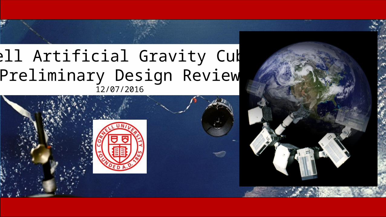
Robert ZubrinRadiation isn't as bad. But you need artificial gravity otherwise astronauts won't be healthy enough for OPS on Mars.
James LoganRadiation will stop any mission in its tracks, both for astronaut health and for NASA regulations.
December 7, 2016 Cornell University Artificial Gravity Slide 3
Motivation
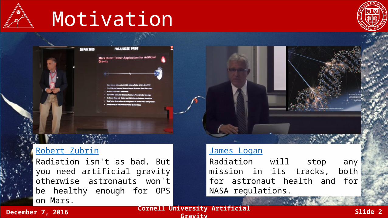
Tethered Satellite Mission History
• Ninth Manned Gemini Mission• Tether did not stay taught• Were able to achieve 0.00015 gees
Zero gravity effects of the human body:
• Bone density drops 1% per month • Bodily fluid pressure distribution change (
https://www.nasa.gov/hrp/bodyinspace)• Loss of muscle mass
TSS-1NASA + Italy 1992
TiPSUS Navy 1996
Gemini XINASA 1966
December 7, 2016 Cornell University Artificial Gravity Slide 4
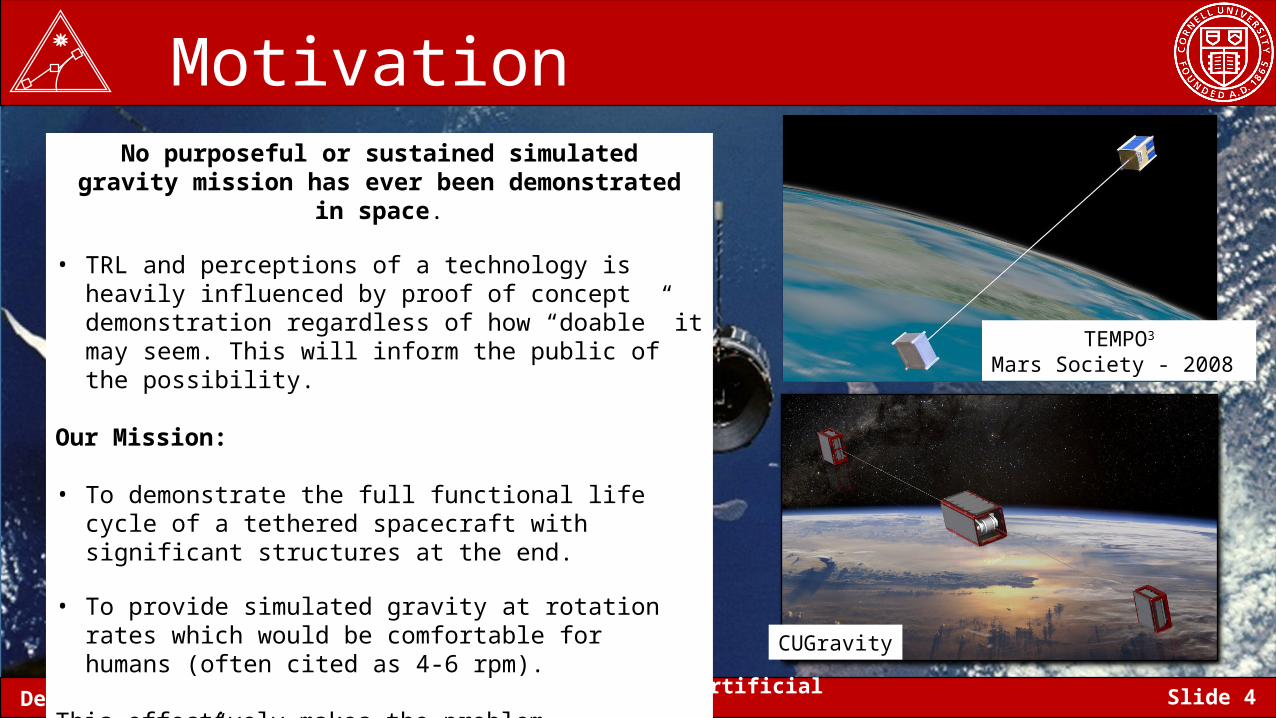
MotivationNo purposeful or sustained simulated gravity mission has ever
been demonstrated in space.
• TRL and perceptions of a technology is heavily influenced by proof of concept demonstration regardless of how “doable” it may seem. This will inform the public of the possibility.
Our Mission:
• To demonstrate the full functional life cycle of a tethered spacecraft with significant structures at the end.
• To provide simulated gravity at rotation rates which would be comfortable for humans (often cited as 4-6 rpm).
This effectively makes the problem “difficult” so that our system is a proper technology demonstration.
TEMPO3
Mars Society - 2008
CUGravity
December 7, 2016 Cornell University Artificial Gravity Slide 5
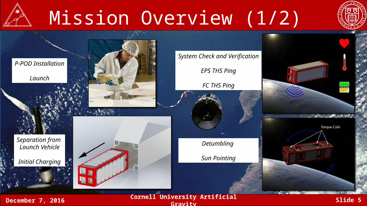
Mission Overview (1/2)
P-POD Installation
Launch
Separation from Launch Vehicle
Initial Charging
System Check and Verification
EPS THS Ping
FC THS Ping
Detumbling
Sun Pointing
December 7, 2016 Cornell University Artificial Gravity Slide 6
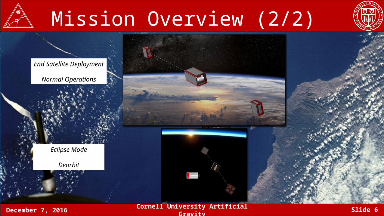
Mission Overview (2/2)
End Satellite Deployment
Normal Operations
Eclipse Mode
Deorbit
December 7, 2016 Cornell University Artificial Gravity Slide 7
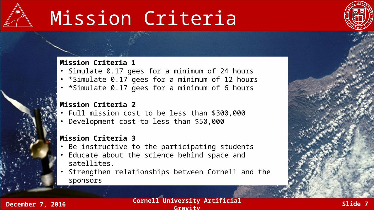
Mission Criteria
Mission Criteria 1• Simulate 0.17 gees for a minimum of 24 hours • *Simulate 0.17 gees for a minimum of 12 hours• *Simulate 0.17 gees for a minimum of 6 hours
Mission Criteria 2 • Full mission cost to be less than $300,000 • Development cost to less than $50,000
Mission Criteria 3• Be instructive to the participating students• Educate about the science behind space and satellites. • Strengthen relationships between Cornell and the sponsors
December 7, 2016 Cornell University Artificial Gravity Slide 8
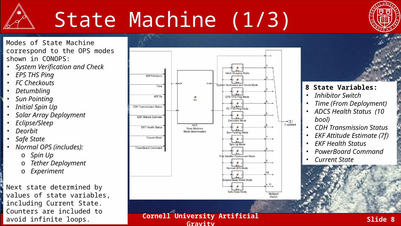
State Machine (1/3)Modes of State Machine correspond to the OPS modes shown in CONOPS:• System Verification and Check• EPS THS Ping• FC Checkouts • Detumbling• Sun Pointing• Initial Spin Up• Solar Array Deployment• Eclipse/Sleep• Deorbit• Safe State• Normal OPS (includes):
o Spin Upo Tether Deploymento Experiment
Next state determined by values of state variables, including Current State. Counters are included to avoid infinite loops.
8 State Variables:• Inhibitor Switch• Time (From Deployment)• ADCS Health Status (10
bool)• CDH Transmission Status• EKF Attitude Estimate (7f)• EKF Health Status• PowerBoard Command• Current State
December 7, 2016 Cornell University Artificial Gravity Slide 9
State Machine (2/3)
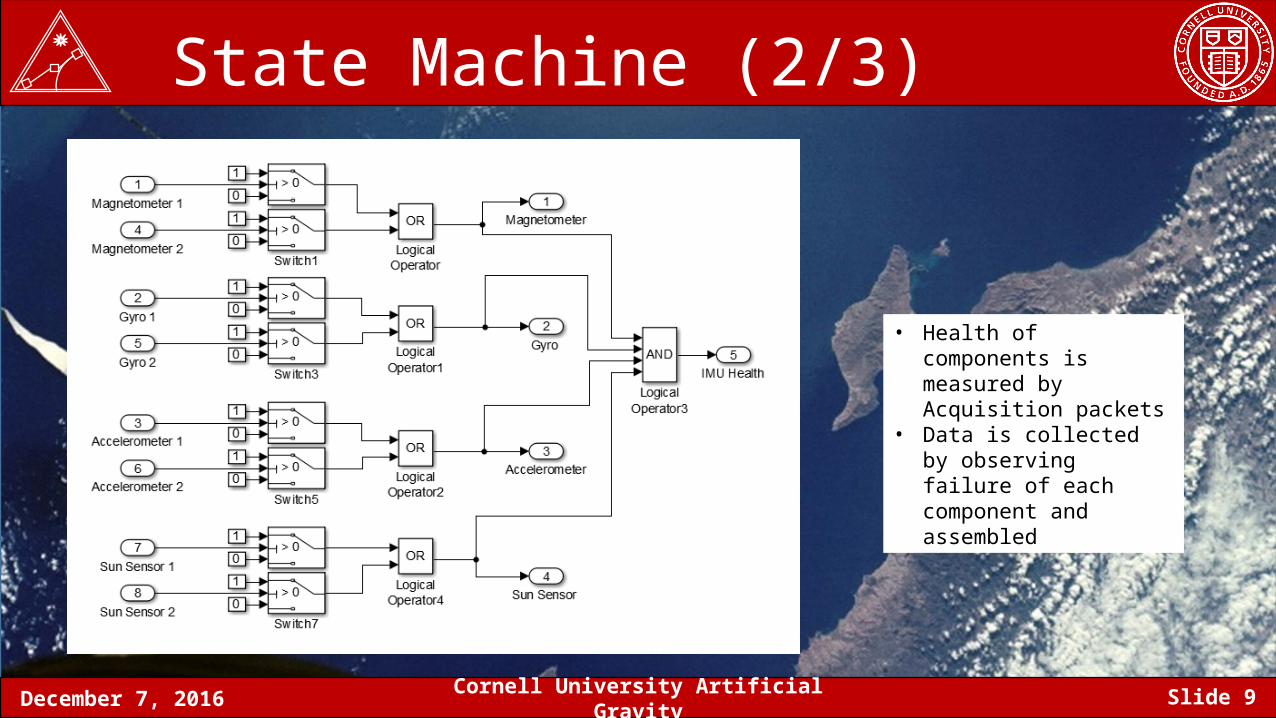
• Health of components is measured by Acquisition packets
• Data is collected by observing failure of each component and assembled
December 7, 2016 Cornell University Artificial Gravity Slide 10
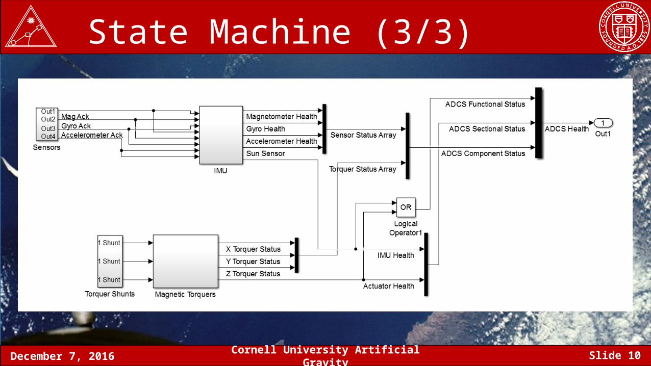
State Machine (3/3)
December 7, 2016 Cornell University Artificial Gravity Slide 11
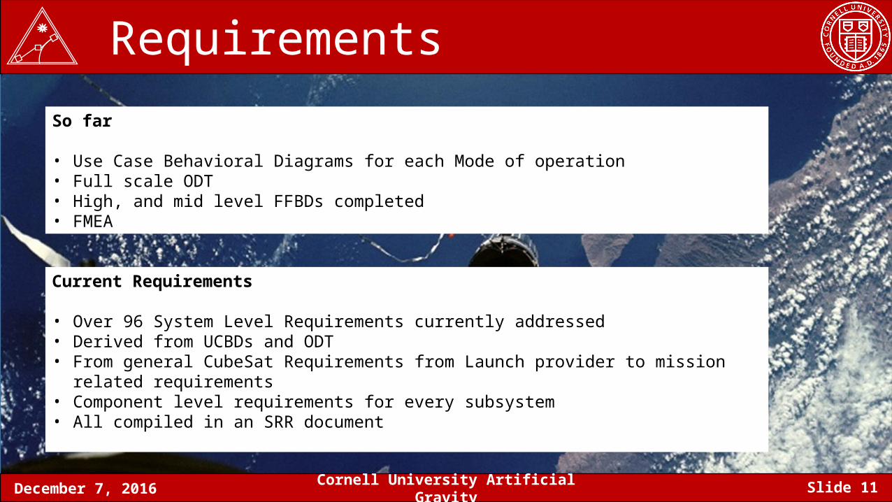
Requirements So far
• Use Case Behavioral Diagrams for each Mode of operation• Full scale ODT• High, and mid level FFBDs completed• FMEA
Current Requirements
• Over 96 System Level Requirements currently addressed• Derived from UCBDs and ODT• From general CubeSat Requirements from Launch provider to mission related requirements• Component level requirements for every subsystem• All compiled in an SRR document
December 7, 2016 Cornell University Artificial Gravity Slide 12
Dynamics Trade
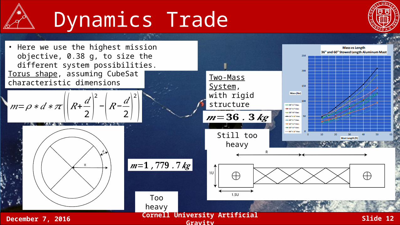
𝑚=𝜌∗𝑑∗𝜋 ((𝑅+𝑑2 )
2
−(𝑅− 𝑑2 )
2) 𝒎=𝟑𝟔 .𝟑𝒌𝒈
Torus shape, assuming CubeSat characteristic dimensions
Two-Mass System, with rigid structure
• Here we use the highest mission objective, 0.38 g, to size the different system possibilities.
𝒎=𝟏 ,𝟕𝟕𝟗 .𝟕𝒌𝒈
Too heavy
Still too heavy
December 7, 2016 Cornell University Artificial Gravity Slide 13
Dynamics Trade
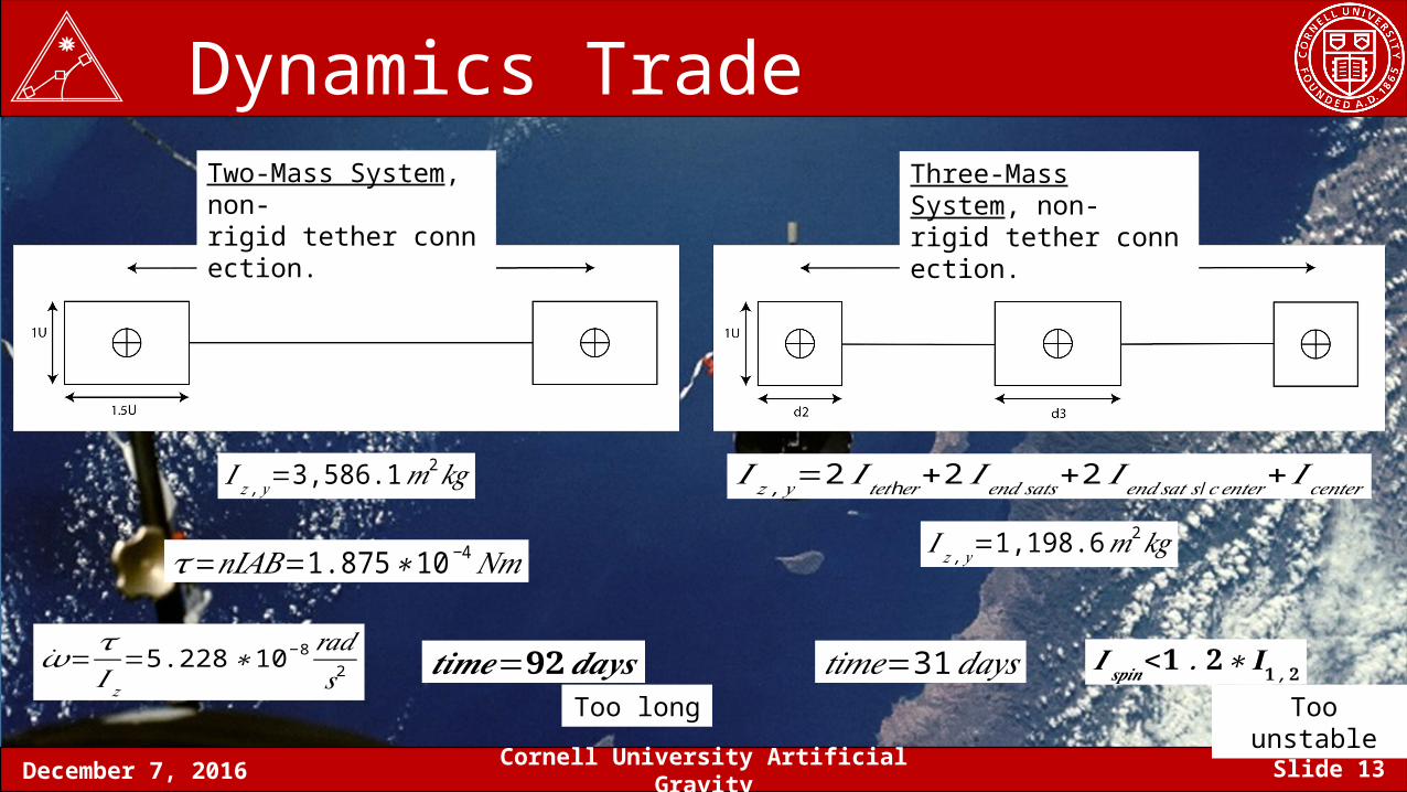
𝐼 𝑧 , 𝑦=3,586.1𝑚2𝑘𝑔
𝜏=𝑛𝐼𝐴𝐵=1.875∗10− 4𝑁𝑚
=𝜏𝐼 𝑧
=5.228∗10−8 𝑟𝑎𝑑𝑠2 𝒕𝒊𝒎𝒆=𝟗𝟐𝒅𝒂𝒚𝒔
𝐼 𝑧 ,𝑦=2 𝐼 h𝑡𝑒𝑡 𝑒𝑟+2 𝐼𝑒𝑛𝑑𝑠𝑎𝑡𝑠+2 𝐼𝑒𝑛𝑑𝑠𝑎𝑡 𝑠 /𝑐 𝑒𝑛𝑡𝑒𝑟+ 𝐼𝑐𝑒𝑛𝑡𝑒𝑟𝐼 𝑧 ,𝑦=1,198.6𝑚2𝑘𝑔
𝑡𝑖𝑚𝑒=31𝑑𝑎𝑦𝑠 𝑰 𝒔𝒑𝒊𝒏<𝟏 .𝟐∗𝐈𝟏 ,𝟐
Two-Mass System, non-rigid tether connection.
Three-Mass System, non-rigid tether connection.
Too long Too unstable
December 7, 2016 Cornell University Artificial Gravity Slide 14
Dynamics Trade
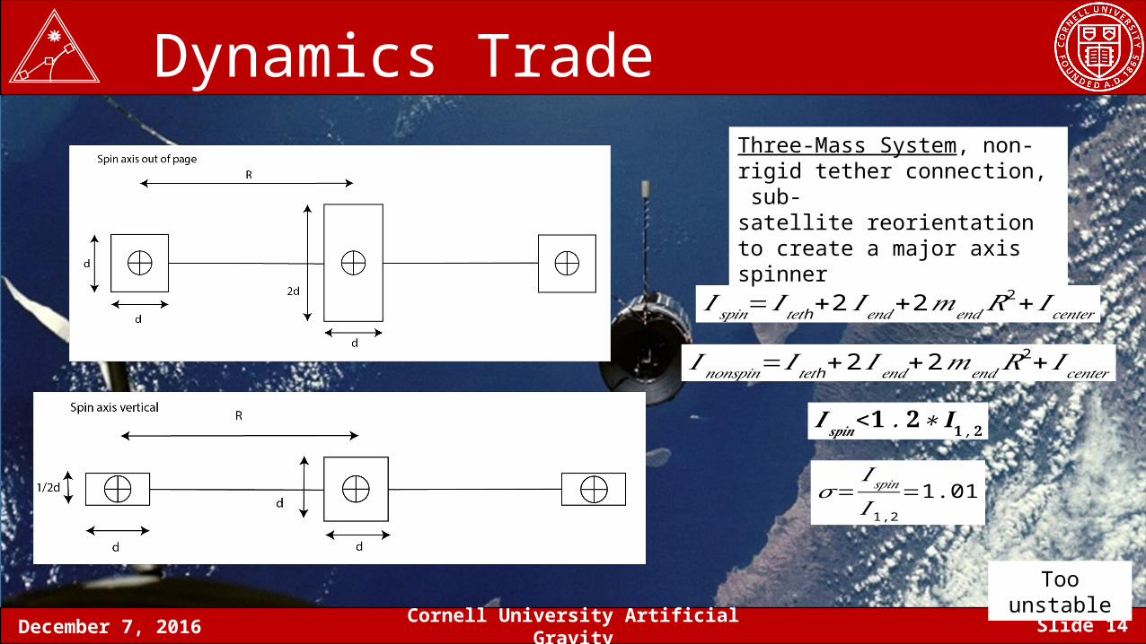
𝐼 𝑠𝑝𝑖𝑛=𝐼 h𝑡𝑒𝑡 +2 𝐼 𝑒𝑛𝑑+2𝑚𝑒𝑛𝑑𝑅2+ 𝐼𝑐𝑒𝑛𝑡𝑒𝑟
𝐼𝑛𝑜𝑛𝑠𝑝𝑖𝑛=𝐼 h𝑡𝑒𝑡 +2 𝐼 𝑒𝑛𝑑+2𝑚𝑒𝑛𝑑𝑅2+ 𝐼𝑐𝑒𝑛𝑡𝑒𝑟
𝑰 𝒔𝒑𝒊𝒏<𝟏 .𝟐∗𝐈𝟏 ,𝟐
Three-Mass System, non-rigid tether connection, sub-satellite reorientation to create a major axis spinner
𝜎=𝐼 𝑠𝑝𝑖𝑛𝐼 1,2
=1.01
Too unstable
December 7, 2016 Cornell University Artificial Gravity Slide 15
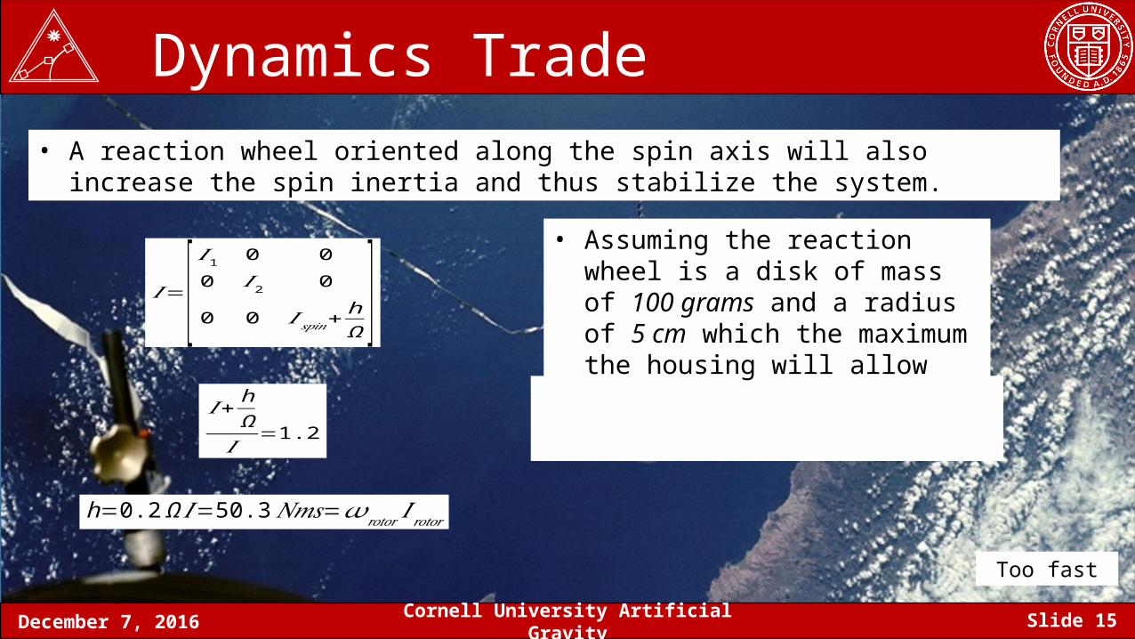
Dynamics Trade• A reaction wheel oriented along the spin axis will also increase the spin inertia and thus
stabilize the system.
𝐼=[ 𝐼 1 0 00 𝐼2 0
0 0 𝐼 𝑠𝑝𝑖𝑛+hΩ ]
𝐼+ hΩ𝐼 =1.2
h=0.2 Ω 𝐼=50.3𝑁𝑚𝑠=𝜔𝑟𝑜𝑡𝑜𝑟 𝐼𝑟𝑜𝑡𝑜𝑟
• Assuming the reaction wheel is a disk of mass of 100 grams and a radius of 5 cm which the maximum the housing will allow
Too fast
December 7, 2016 Cornell University Artificial Gravity Slide 16
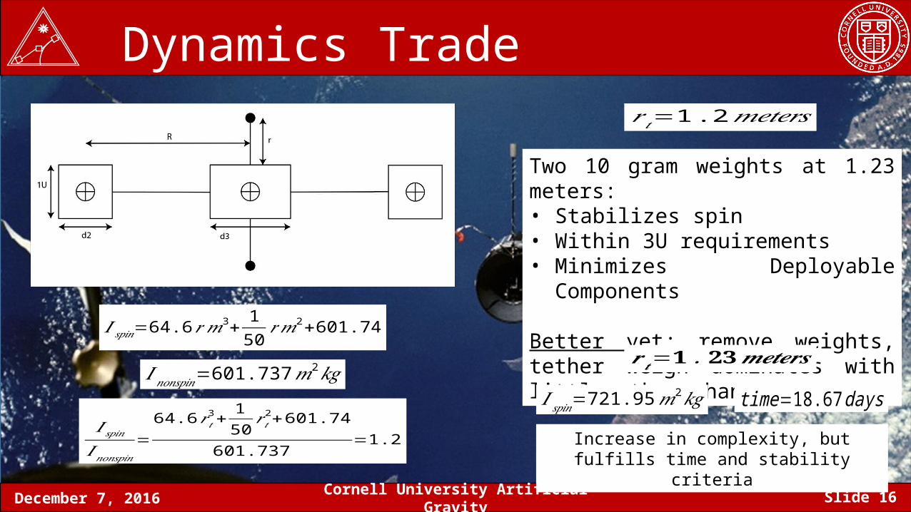
Dynamics Trade
𝐼 𝑠𝑝𝑖𝑛=64.6𝑟𝑚3+150 𝑟𝑚
2+601.74
𝐼𝑛𝑜𝑛𝑠𝑝𝑖𝑛=601.737𝑚2𝑘𝑔
𝐼 𝑠𝑝𝑖𝑛𝐼𝑛𝑜𝑛𝑠𝑝𝑖𝑛
=64.6𝑟 𝑡3+
150 𝑟 𝑡
2+601.74
601.737=1.2
𝑟 𝑡=1 .2𝑚𝑒𝑡𝑒𝑟𝑠
Two 10 gram weights at 1.23 meters:• Stabilizes spin• Within 3U requirements• Minimizes Deployable Components
Better yet; remove weights, tether weigh dominates with little other change
𝐼 𝑠𝑝𝑖𝑛=721.95𝑚2𝑘𝑔
𝒓 𝒕=𝟏 .𝟐𝟑𝒎𝒆𝒕𝒆𝒓𝒔
time=18.67 daysIncrease in complexity, but fulfills time and
stability criteria
December 7, 2016 Cornell University Artificial Gravity Slide 17
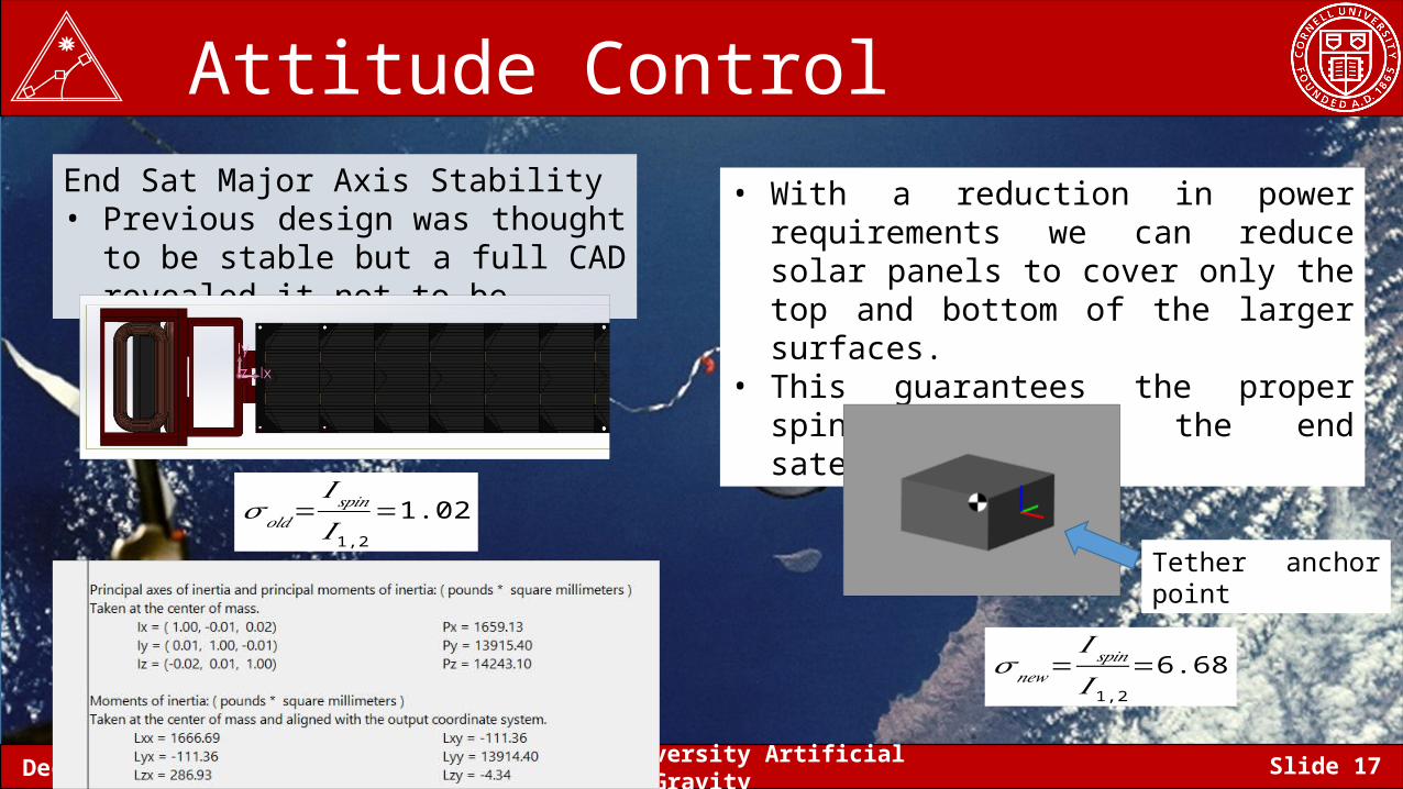
Attitude Control End Sat Major Axis Stability• Previous design was thought to be
stable but a full CAD revealed it not to be
𝜎 𝑜𝑙𝑑=𝐼 𝑠𝑝𝑖𝑛𝐼1,2
=1.02
• With a reduction in power requirements we can reduce solar panels to cover only the top and bottom of the larger surfaces.
• This guarantees the proper spin axis for the end satellites
Tether anchor point
𝜎 𝑛𝑒𝑤=𝐼 𝑠𝑝𝑖𝑛𝐼 1,2
=6.68
December 7, 2016 Cornell University Artificial Gravity Slide 18
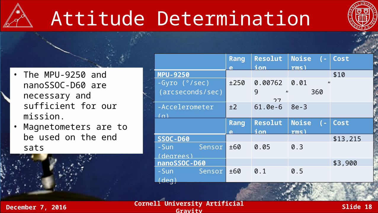
Attitude Determination
Range Resolution Noise (-rms) CostMPU-9250 $10-Gyro (º/sec)
(arcseconds/sec)±250 0.007629
27”0.01
360”
-Accelerometer (g) ±2 61.0e-6 8e-3 -Magnetometer (μT) ±1200 0.293 N/A
• The MPU-9250 and nanoSSOC-D60 are necessary and sufficient for our mission.
• Magnetometers are to be used on the end sats Range Resolution Noise (-rms) Cost
SSOC-D60 $13,215-Sun Sensor (degrees) ±60 0.05 0.3nanoSSOC-D60 $3,900-Sun Sensor (deg) ±60 0.1 0.5
December 7, 2016 Cornell University Artificial Gravity Slide 19
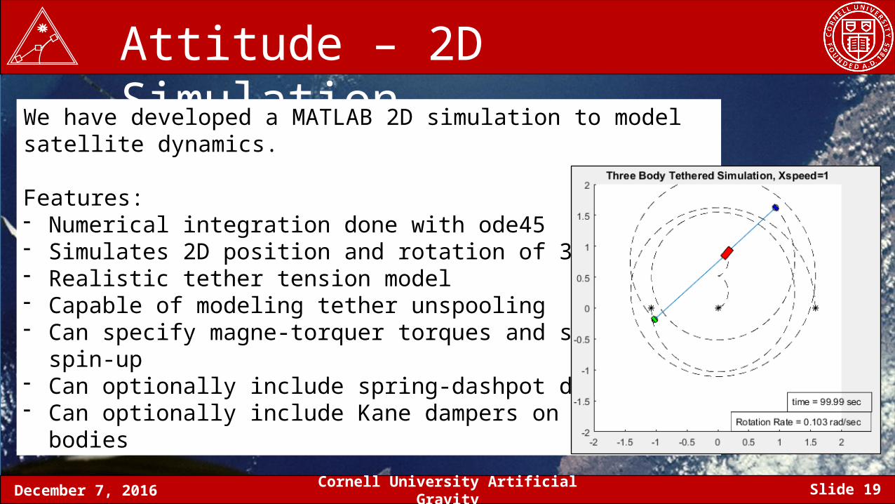
Attitude – 2D SimulationWe have developed a MATLAB 2D simulation to model satellite dynamics.
Features:- Numerical integration done with ode45- Simulates 2D position and rotation of 3 bodies- Realistic tether tension model- Capable of modeling tether unspooling- Can specify magne-torquer torques and system spin-up- Can optionally include spring-dashpot damper- Can optionally include Kane dampers on all three bodies
December 7, 2016 Cornell University Artificial Gravity Slide 20
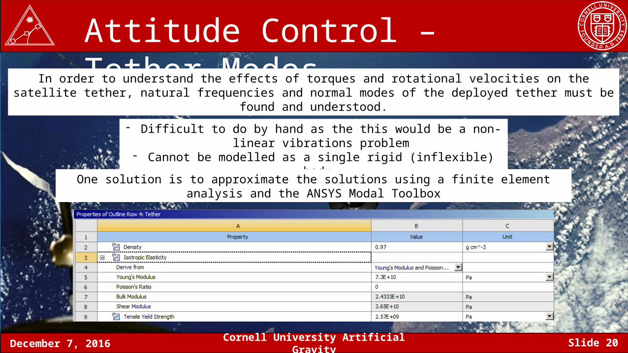
Attitude Control – Tether ModesIn order to understand the effects of torques and rotational velocities on the satellite tether, natural frequencies and normal
modes of the deployed tether must be found and understood.
- Difficult to do by hand as the this would be a non-linear vibrations problem- Cannot be modelled as a single rigid (inflexible) body.
One solution is to approximate the solutions using a finite element analysis and the ANSYS Modal Toolbox
December 7, 2016 Cornell University Artificial Gravity Slide 21
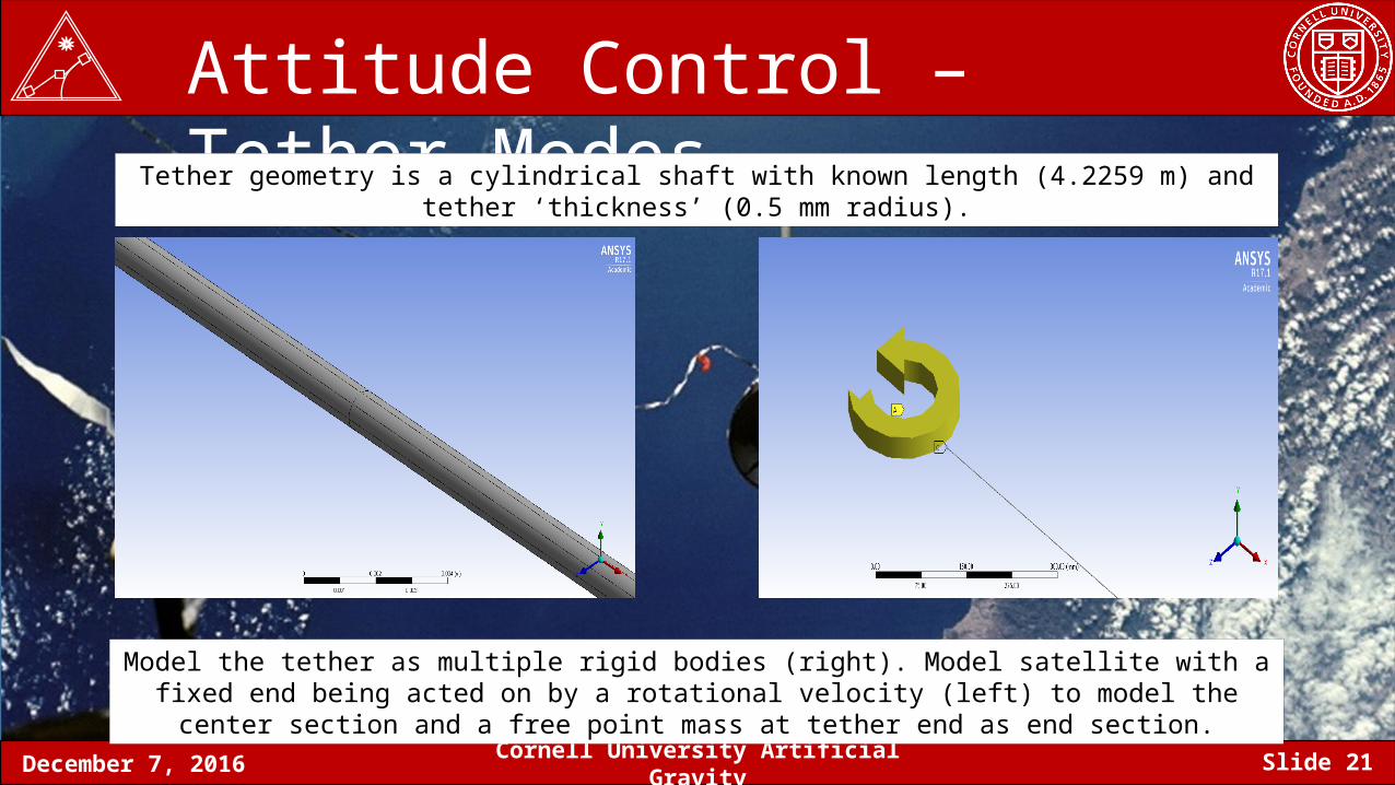
Attitude Control – Tether ModesTether geometry is a cylindrical shaft with known length (4.2259 m) and tether ‘thickness’ (0.5 mm radius).
Model the tether as multiple rigid bodies (right). Model satellite with a fixed end being acted on by a rotational velocity (left) to model the center section and a free point mass at tether end as end section.
December 7, 2016 Cornell University Artificial Gravity Slide 22
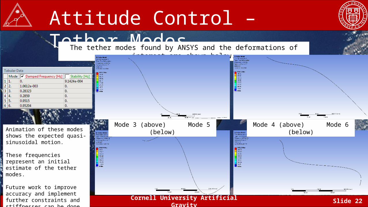
Attitude Control – Tether ModesThe tether modes found by ANSYS and the deformations of interest are shown below.
Mode 3 (above) Mode 5 (below) Mode 4 (above) Mode 6 (below)Animation of these modes shows the expected quasi-sinusoidal motion.
These frequencies represent an initial estimate of the tether modes.
Future work to improve accuracy and implement further constraints and stiffnesses can be done.
December 7, 2016 Cornell University Artificial Gravity Slide 23
Attitude – Damping ReqAny perturbation from a stable state will cause the three body tethered system to oscillate.
First significant 2D mode – bouncing off end of tether- If the system is rotating and the tether has slack, the tether will become briefly taut, then become slack again- Brief high tension on tether- Brief high torque on center-sat and end-sat
Second significant 2D mode – rotational oscillation of bodies- If the angular velocity of the three sats do not all match the angular velocity of the system, there will be rotational oscillation- The sats will all have an average angular velocity equal to that of the system, with an additional oscillatory component- Amplitude of the rotational oscillations can be very large, could be around the same magnitude as
Challenges- Difficultly in attitude determination- Difficultly in fulfillment of mission objectives- Highly sensitive to controller inputs and disturbances- High sensitivity makes it difficult to simulate/predict dynamics for long time periods
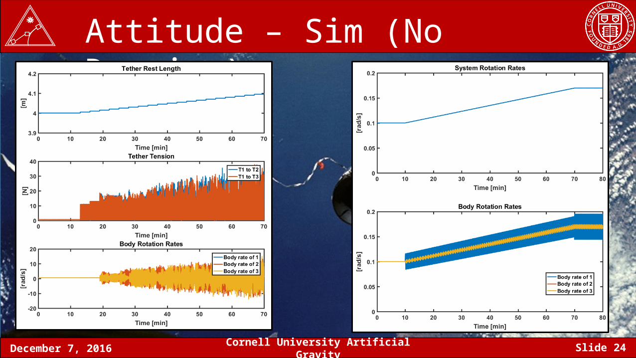
December 7, 2016 Cornell University Artificial Gravity Slide 24
Attitude – Sim (No Damping)
December 7, 2016 Cornell University Artificial Gravity Slide 25
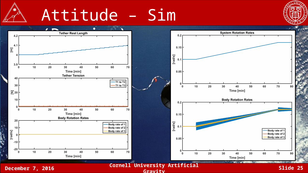
Attitude – Sim (Damping)
December 7, 2016 Cornell University Artificial Gravity Slide 26
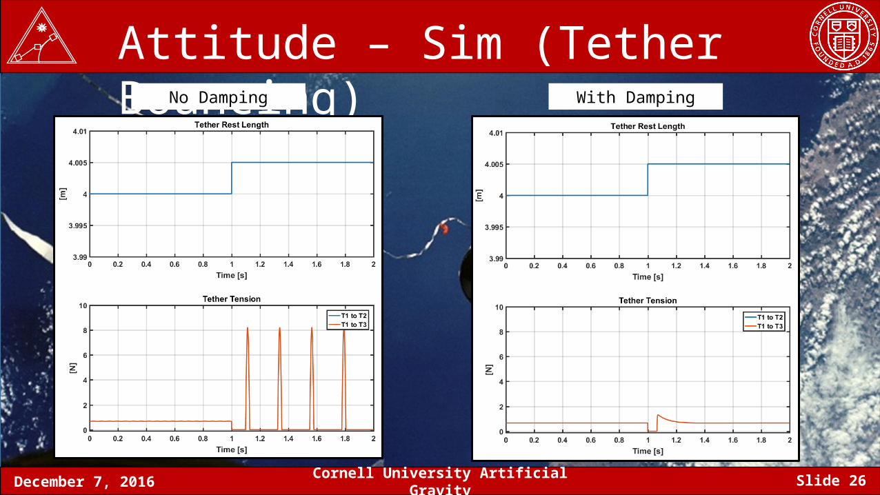
Attitude – Sim (Tether Bouncing)No Damping With Damping
December 7, 2016 Cornell University Artificial Gravity Slide 27
Attitude – Damping (Just Tether)
• Some form of energy dissipation is necessary to bring the system from the oscillating state (high energy) to the steady state (low energy).
• The tether material will have some non-zero damping, but likely very small.
• As , the oscillations will go to zero, but we do not know how quickly this will occur.
• Without knowing an accurate value for the tether material damping constant, it is difficult to predict how long it will take to damp out oscillations – might be longer than our mission requirements.
December 7, 2016 Cornell University Artificial Gravity Slide 28
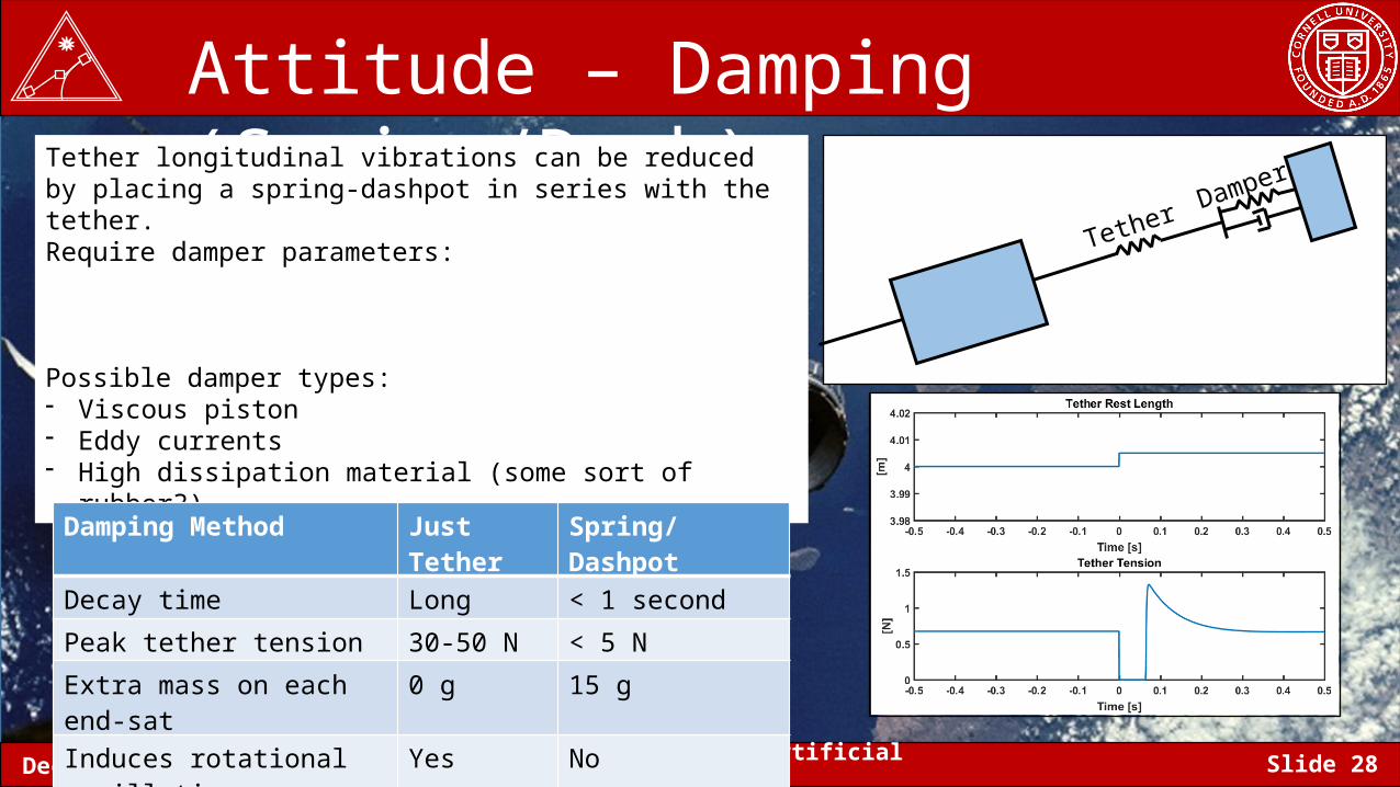
Attitude – Damping (Spring/Dash)Tether longitudinal vibrations can be reduced by placing a spring-dashpot in series with the tether.Require damper parameters:
Possible damper types:- Viscous piston- Eddy currents- High dissipation material (some sort of rubber?)
TetherDamper
Damping Method Just Tether Spring/Dashpot
Decay time Long < 1 second
Peak tether tension 30-50 N < 5 N
Extra mass on each end-sat 0 g 15 g
Induces rotational oscillations Yes No
December 7, 2016 Cornell University Artificial Gravity Slide 29
Attitude – Damping (Torque Coils)• Rotational oscillations can be damped out by using active control if all three satellites
have torque coils.
• This damping can be simulated by using a simple proportional controller. Apply a torque proportional to the error between the actual rotation rate and the desired rotation rate.
• We already have torque coils for the middle sat, so this can be used to damp out rotational oscillations in the middle sat.
• We could also choose to have magne-torquers on the end sats, but there are other disadvantages to doing so.
December 7, 2016 Cornell University Artificial Gravity Slide 30
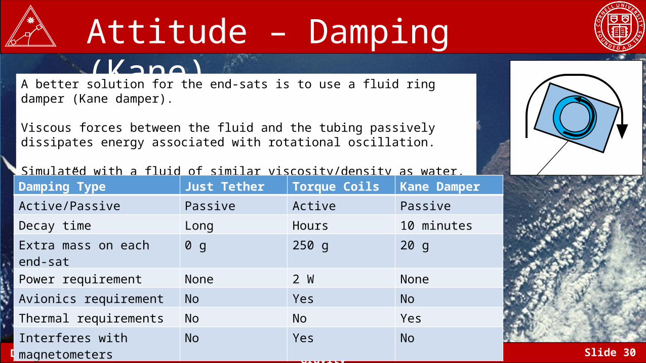
Attitude – Damping (Kane)A better solution for the end-sats is to use a fluid ring damper (Kane damper).
Viscous forces between the fluid and the tubing passively dissipates energy associated with rotational oscillation.
Simulated with a fluid of similar viscosity/density as water, with ¼” inner diameter tubing.
Damping Type Just Tether Torque Coils Kane DamperActive/Passive Passive Active Passive
Decay time Long Hours 10 minutes
Extra mass on each end-sat 0 g 250 g 20 g
Power requirement None 2 W None
Avionics requirement No Yes No
Thermal requirements No No Yes
Interferes with magnetometers No Yes No
December 7, 2016 Cornell University Artificial Gravity Slide 31
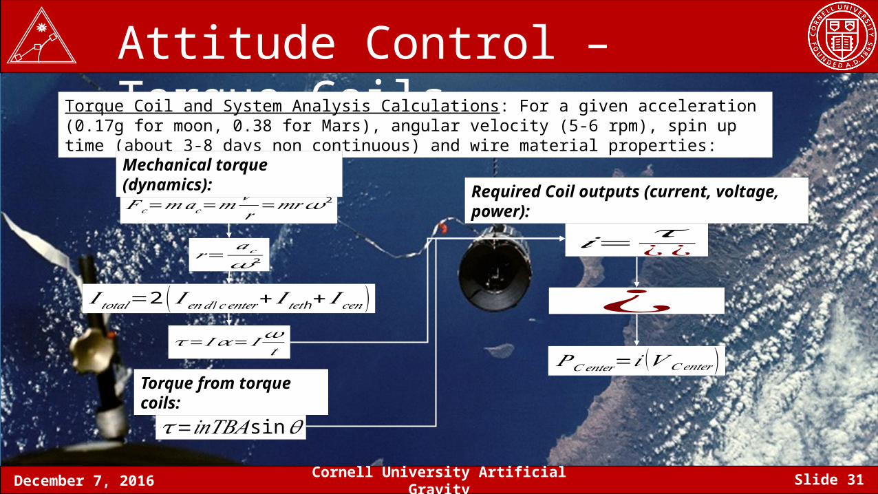
Attitude Control – Torque CoilsTorque Coil and System Analysis Calculations: For a given acceleration (0.17g for moon, 0.38 for Mars), angular velocity (5-6 rpm), spin up time (about 3-8 days non continuous) and wire material properties:
𝐹 𝑐=𝑚𝑎𝑐=𝑚𝑣2
𝑟 =𝑚𝑟𝜔2
𝑟=𝑎𝑐𝜔2
𝐼 𝑡𝑜𝑡𝑎𝑙=2 ( 𝐼𝑒𝑛𝑑 /𝑐𝑒𝑛𝑡𝑒𝑟+ 𝐼 h𝑡𝑒𝑡 +𝐼 𝑐𝑒𝑛)
𝜏= 𝐼 𝛼=𝐼 𝜔𝑡
𝜏=𝑖𝑛𝑇𝐵𝐴sin𝜃
𝑖= 𝜏¿ ¿
¿
𝑃𝐶𝑒𝑛𝑡𝑒𝑟=𝑖 (𝑉 𝐶𝑒𝑛𝑡𝑒𝑟 )
Mechanical torque (dynamics):
Torque from torque coils:
Required Coil outputs (current, voltage, power):
December 7, 2016 Cornell University Artificial Gravity Slide 32
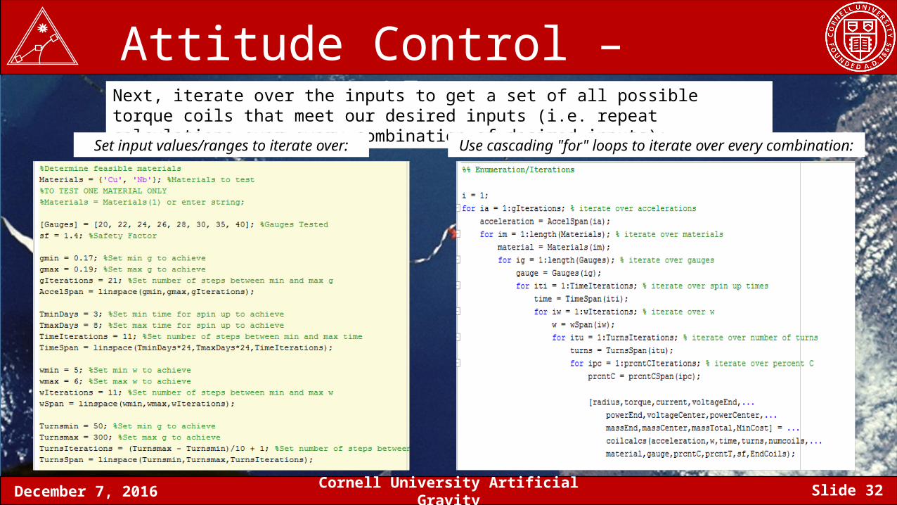
Attitude Control – Torque CoilsNext, iterate over the inputs to get a set of all possible torque coils that meet our desired inputs (i.e. repeat calculations over every combination of desired inputs):
Set input values/ranges to iterate over: Use cascading "for" loops to iterate over every combination:
December 7, 2016 Cornell University Artificial Gravity Slide 33
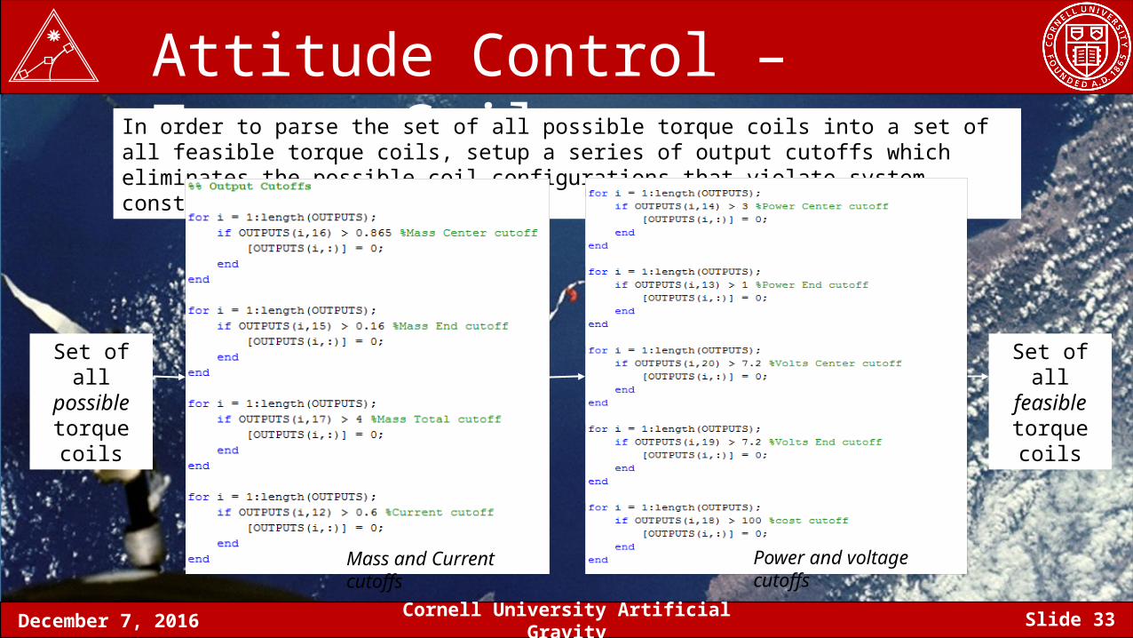
Attitude Control – Torque CoilsIn order to parse the set of all possible torque coils into a set of all feasible torque coils, setup a series of output cutoffs which eliminates the possible coil configurations that violate system constraints:
Mass and Current cutoffs Power and voltage cutoffs
Set of all possible
torque coils
Set of all feasible
torque coils
December 7, 2016 Cornell University Artificial Gravity Slide 34
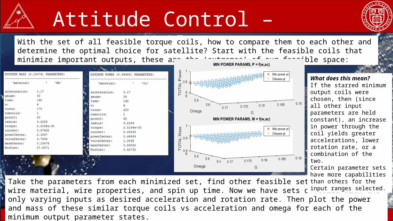
Attitude Control – Torque CoilsWith the set of all feasible torque coils, how to compare them to each other and determine the optimal choice for satellite? Start with the feasible coils that minimize important outputs, these are the ‘extremes’ of our feasible space:
Take the parameters from each minimized set, find other feasible sets with the same wire material, wire properties, and spin up time. Now we have sets of coils with the only varying inputs as desired acceleration and rotation rate. Then plot the power and mass of these similar torque coils vs acceleration and omega for each of the minimum output parameter states.
What does this mean?If the starred minimum output coils were chosen, then (since all other input parameters are held constant), an increase in power through the coil yields greater accelerations, lower rotation rate, or a combination of the two.Certain parameter sets have more capabilities than others for the input ranges selected.
December 7, 2016 Cornell University Artificial Gravity Slide 35
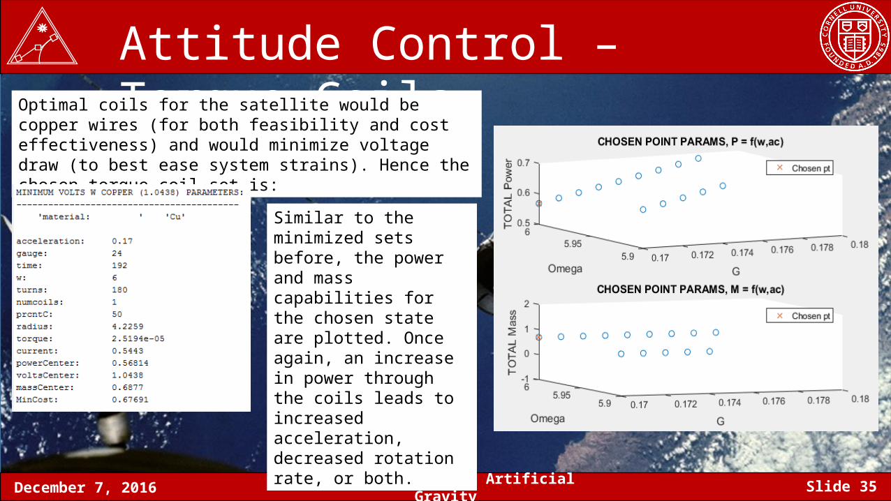
Attitude Control – Torque CoilsOptimal coils for the satellite would be copper wires (for both feasibility and cost effectiveness) and would minimize voltage draw (to best ease system strains). Hence the chosen torque coil set is:
Similar to the minimized sets before, the power and mass capabilities for the chosen state are plotted. Once again, an increase in power through the coils leads to increased acceleration, decreased rotation rate, or both.
December 7, 2016 Cornell University Artificial Gravity Slide 36
• Goals and design mindset:• Design a modular and robust system that is effective and at least an order of magnitude cheaper than COTS solutions.• Reuse of work --> eg: same power circuitry on all three satellite, very similar code, similar comm architecture
• Hardware• End Satellite
• transmit acceleration, magnetic field, and sun sensor data• Middle Satellite
• Apply torque to 3-body system with the goal to spin up and generate outward forces • Communicate with end satellites to take data from them • Downlink data using the iridium constellation • Apply system changes with accordance to uplinked commands
Avionics Overview
December 7, 2016 Cornell University Artificial Gravity Slide 37
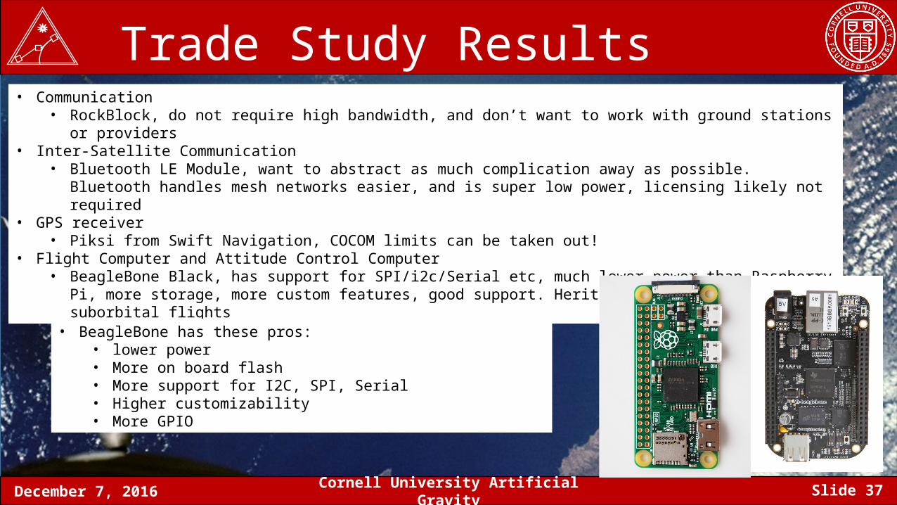
Trade Study Results• Communication
• RockBlock, do not require high bandwidth, and don’t want to work with ground stations or providers• Inter-Satellite Communication
• Bluetooth LE Module, want to abstract as much complication away as possible. Bluetooth handles mesh networks easier, and is super low power, licensing likely not required
• GPS receiver• Piksi from Swift Navigation, COCOM limits can be taken out!
• Flight Computer and Attitude Control Computer• BeagleBone Black, has support for SPI/i2c/Serial etc, much lower power than Raspberry Pi, more storage, more custom
features, good support. Heritage with BURPG on suborbital flights
• BeagleBone has these pros:• lower power• More on board flash• More support for I2C, SPI, Serial • Higher customizability• More GPIO
December 7, 2016 Cornell University Artificial Gravity Slide 38
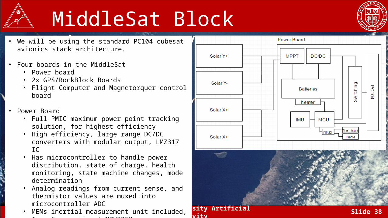
MiddleSat Block Diagrams (1/2)• We will be using the standard PC104 cubesat avionics stack
architecture.
• Four boards in the MiddleSat• Power board• 2x GPS/RockBlock Boards• Flight Computer and Magnetorquer control board
• Power Board• Full PMIC maximum power point tracking solution, for
highest efficiency• High efficiency, large range DC/DC converters with modular
output, LMZ317 IC• Has microcontroller to handle power distribution, state of
charge, health monitoring, state machine changes, mode determination
• Analog readings from current sense, and thermistor values are muxed into microcontroller ADC
• MEMs inertial measurement unit included, InvenSense chipset MPU9250
• Feedback loop for controlling temperature of batteries
December 7, 2016 Cornell University Artificial Gravity Slide 39
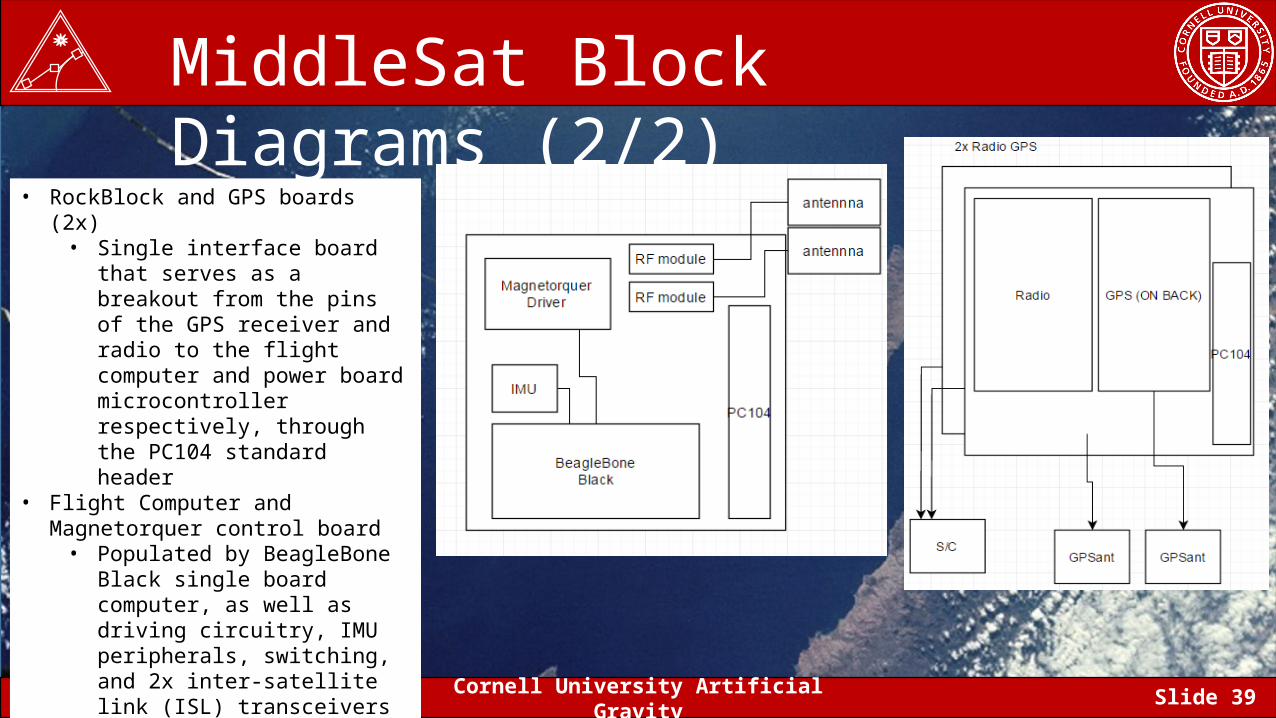
MiddleSat Block Diagrams (2/2)
• RockBlock and GPS boards (2x)• Single interface board that serves as
a breakout from the pins of the GPS receiver and radio to the flight computer and power board microcontroller respectively, through the PC104 standard header
• Flight Computer and Magnetorquer control board
• Populated by BeagleBone Black single board computer, as well as driving circuitry, IMU peripherals, switching, and 2x inter-satellite link (ISL) transceivers
December 7, 2016 Cornell University Artificial Gravity Slide 40
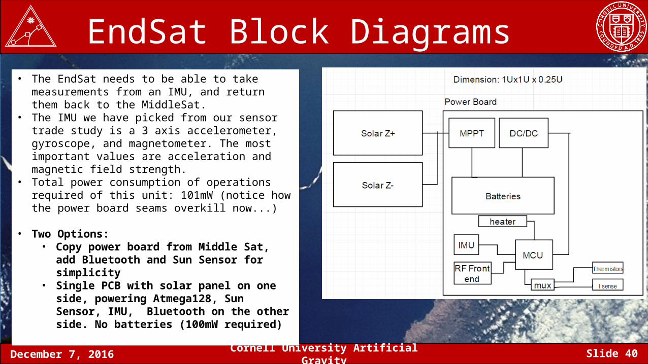
EndSat Block Diagrams • The EndSat needs to be able to take measurements from an
IMU, and return them back to the MiddleSat.• The IMU we have picked from our sensor trade study is a 3
axis accelerometer, gyroscope, and magnetometer. The most important values are acceleration and magnetic field strength.
• Total power consumption of operations required of this unit: 101mW (notice how the power board seams overkill now...)
• Two Options:• Copy power board from Middle Sat, add Bluetooth
and Sun Sensor for simplicity• Single PCB with solar panel on one side, powering
Atmega128, Sun Sensor, IMU, Bluetooth on the other side. No batteries (100mW required)
December 7, 2016 Cornell University Artificial Gravity Slide 41
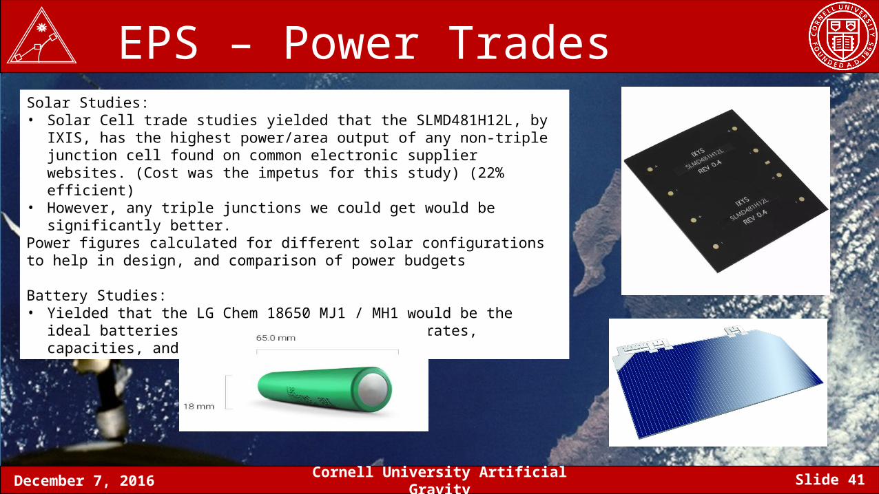
EPS – Power Trades Solar Studies:• Solar Cell trade studies yielded that the SLMD481H12L, by IXIS, has the highest
power/area output of any non-triple junction cell found on common electronic supplier websites. (Cost was the impetus for this study) (22% efficient)
• However, any triple junctions we could get would be significantly better.Power figures calculated for different solar configurations to help in design, and comparison of power budgets
Battery Studies:• Yielded that the LG Chem 18650 MJ1 / MH1 would be the ideal batteries. Good charge
and discharge rates, capacities, and heritage in other cubesats
December 7, 2016 Cornell University Artificial Gravity Slide 42
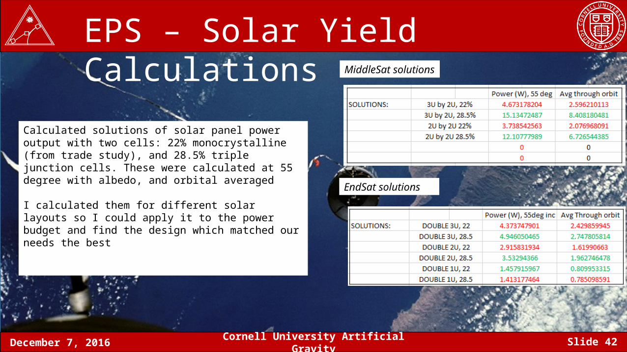
EPS – Solar Yield Calculations
Calculated solutions of solar panel power output with two cells: 22% monocrystalline (from trade study), and 28.5% triple junction cells. These were calculated at 55 degree with albedo, and orbital averaged
I calculated them for different solar layouts so I could apply it to the power budget and find the design which matched our needs the best
MiddleSat solutions
EndSat solutions
December 7, 2016 Cornell University Artificial Gravity Slide 43
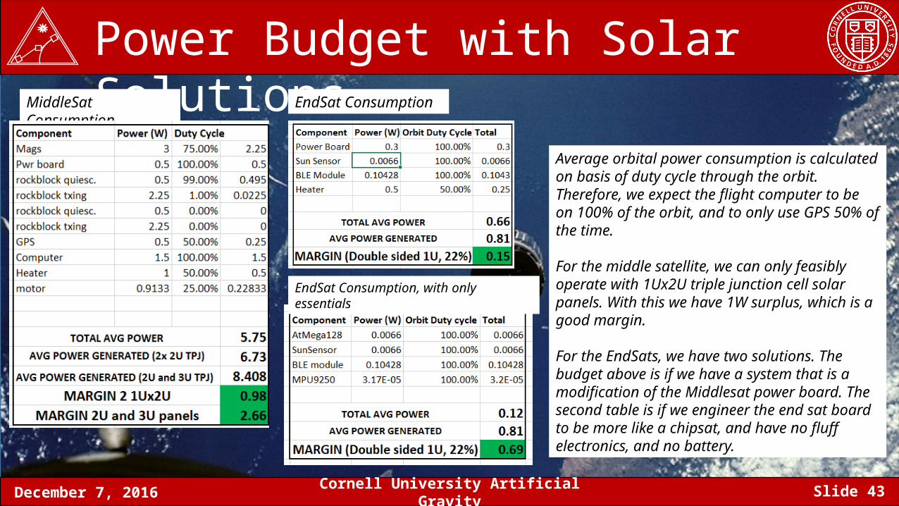
MiddleSat Consumption
Power Budget with Solar SolutionsEndSat Consumption
Average orbital power consumption is calculated on basis of duty cycle through the orbit. Therefore, we expect the flight computer to be on 100% of the orbit, and to only use GPS 50% of the time.
For the middle satellite, we can only feasibly operate with 1Ux2U triple junction cell solar panels. With this we have 1W surplus, which is a good margin.
For the EndSats, we have two solutions. The budget above is if we have a system that is a modification of the Middlesat power board. The second table is if we engineer the end sat board to be more like a chipsat, and have no fluff electronics, and no battery.
EndSat Consumption, with only essentials
December 7, 2016 Cornell University Artificial Gravity Slide 44
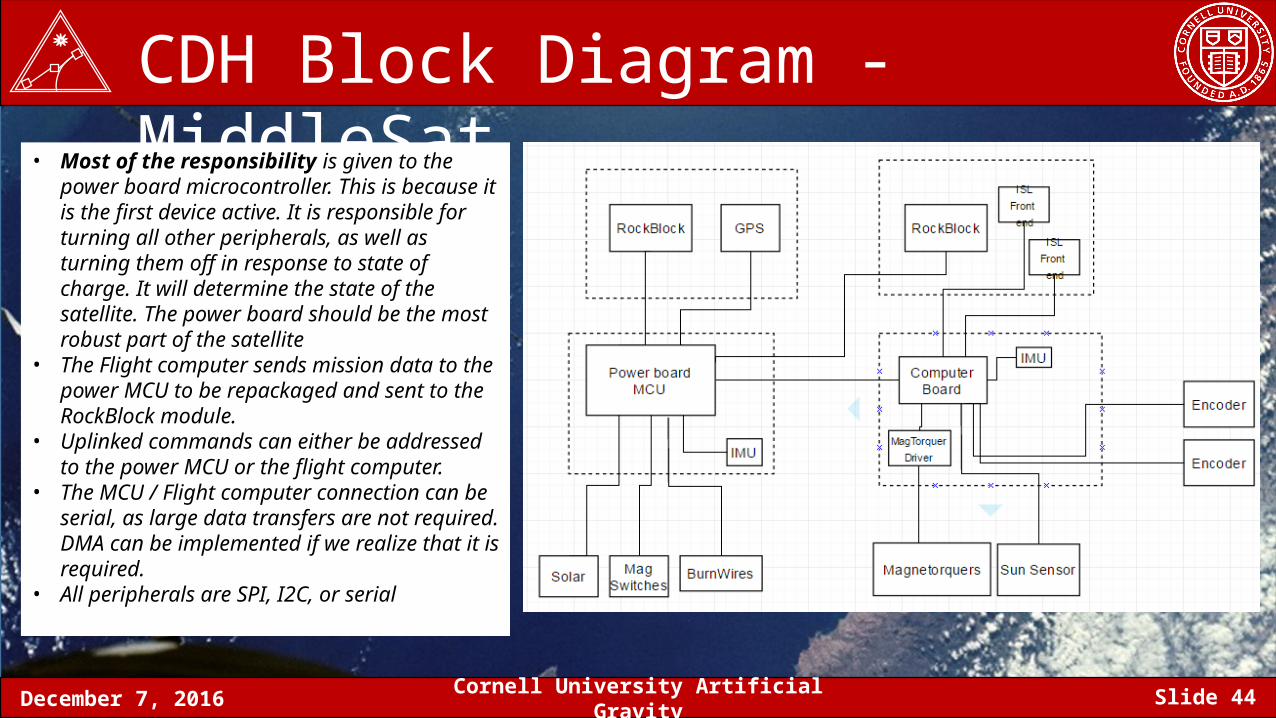
CDH Block Diagram - MiddleSat• Most of the responsibility is given to the power
board microcontroller. This is because it is the first device active. It is responsible for turning all other peripherals, as well as turning them off in response to state of charge. It will determine the state of the satellite. The power board should be the most robust part of the satellite
• The Flight computer sends mission data to the power MCU to be repackaged and sent to the RockBlock module.
• Uplinked commands can either be addressed to the power MCU or the flight computer.
• The MCU / Flight computer connection can be serial, as large data transfers are not required. DMA can be implemented if we realize that it is required.
• All peripherals are SPI, I2C, or serial
December 7, 2016 Cornell University Artificial Gravity Slide 45
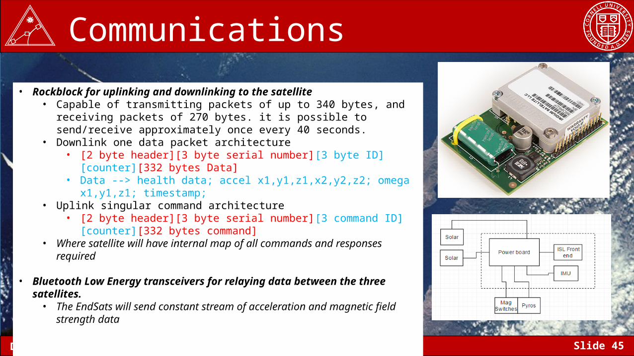
Communications
• Rockblock for uplinking and downlinking to the satellite• Capable of transmitting packets of up to 340 bytes, and receiving packets of 270
bytes. it is possible to send/receive approximately once every 40 seconds.• Downlink one data packet architecture
• [2 byte header][3 byte serial number][3 byte ID][counter][332 bytes Data] • Data --> health data; accel x1,y1,z1,x2,y2,z2; omega x1,y1,z1; timestamp;
• Uplink singular command architecture • [2 byte header][3 byte serial number][3 command ID][counter][332 bytes
command] • Where satellite will have internal map of all commands and responses required
• Bluetooth Low Energy transceivers for relaying data between the three satellites.• The EndSats will send constant stream of acceleration and magnetic field strength
data
December 7, 2016 Cornell University Artificial Gravity Slide 46
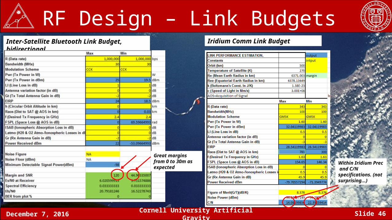
RF Design – Link BudgetsInter-Satellite Bluetooth Link Budget, bidirectional
Great margins from 0 to 30m as expected
Iridium Comm Link Budget
Within Iridium Prec and C/N specifications. (not surprising...)
December 7, 2016 Cornell University Artificial Gravity Slide 47
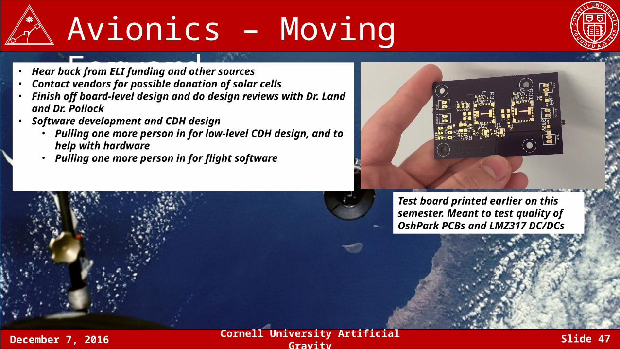
Avionics – Moving Forward• Hear back from ELI funding and other sources• Contact vendors for possible donation of solar cells• Finish off board-level design and do design reviews with Dr. Land and Dr.
Pollock• Software development and CDH design
• Pulling one more person in for low-level CDH design, and to help with hardware
• Pulling one more person in for flight software
Test board printed earlier on this semester. Meant to test quality of OshPark PCBs and LMZ317 DC/DCs
December 7, 2016 Cornell University Artificial Gravity Slide 48
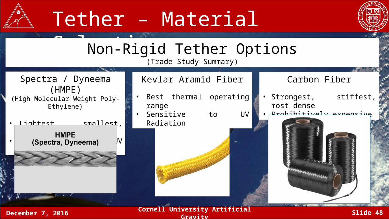
Tether – Material Selection Non-Rigid Tether Options
(Trade Study Summary)
Spectra / Dyneema (HMPE)(High Molecular Weight Poly-Ethylene)
• Lightest, smallest, cheapest• Strongest to UV Radiation
Kevlar Aramid Fiber
• Best thermal operating range• Sensitive to UV Radiation
Carbon Fiber
• Strongest, stiffest, most dense• Prohibitively expensive
December 7, 2016 Cornell University Artificial Gravity Slide 49
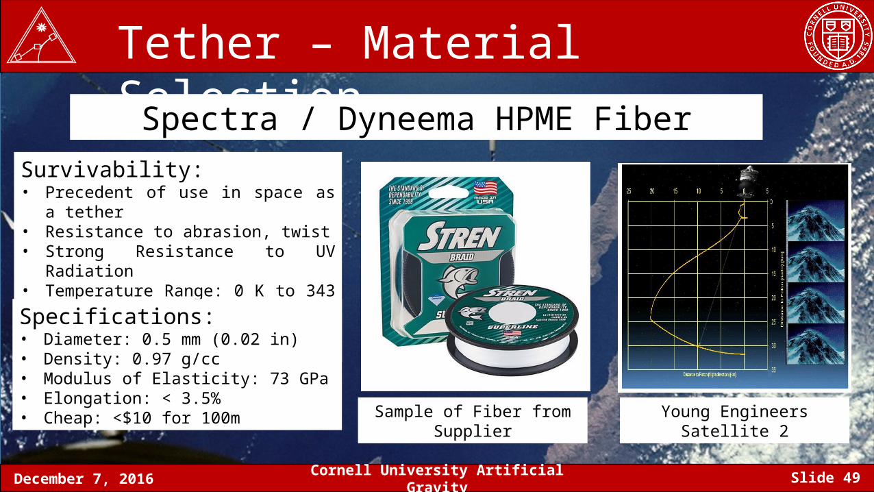
Tether – Material Selection Spectra / Dyneema HPME Fiber
Survivability:• Precedent of use in space as a tether• Resistance to abrasion, twist• Strong Resistance to UV Radiation• Temperature Range: 0 K to 343 K (70° C)• Break Strength: 89 N (20 lbf) (or higher)
Specifications:• Diameter: 0.5 mm (0.02 in)• Density: 0.97 g/cc• Modulus of Elasticity: 73 GPa• Elongation: < 3.5%• Cheap: <$10 for 100m Sample of Fiber from Supplier Young Engineers Satellite 2
December 7, 2016 Cornell University Artificial Gravity Slide 50
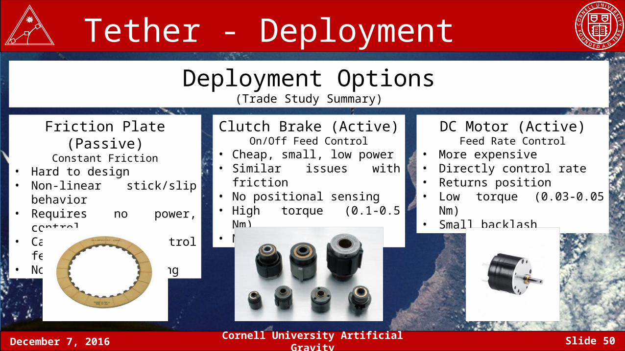
Tether - Deployment Deployment Options
(Trade Study Summary)
Friction Plate (Passive)Constant Friction
• Hard to design• Non-linear stick/slip behavior• Requires no power, control• Can’t directly control feed rate• No positional sensing
Clutch Brake (Active)On/Off Feed Control
• Cheap, small, low power• Similar issues with friction• No positional sensing• High torque (0.1-0.5 Nm)• No backlash
DC Motor (Active)Feed Rate Control
• More expensive• Directly control rate• Returns position• Low torque (0.03-0.05 Nm)• Small backlash
December 7, 2016 Cornell University Artificial Gravity Slide 51
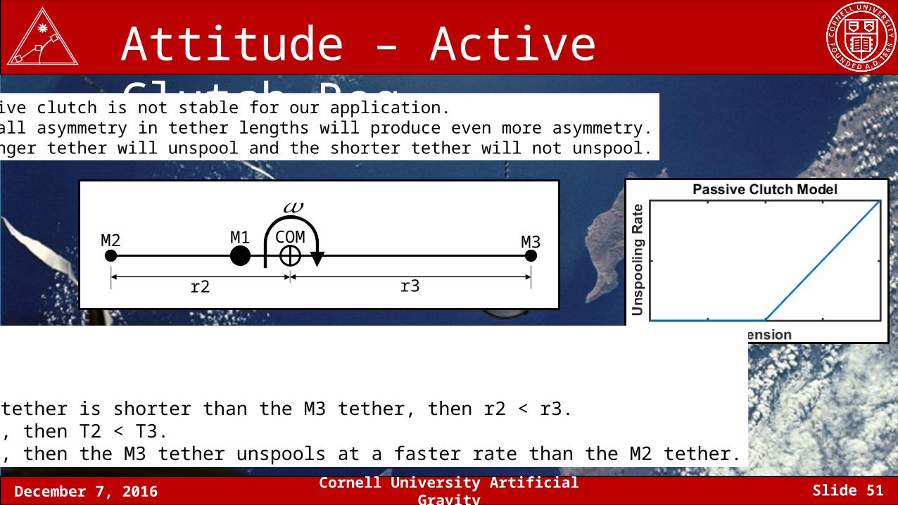
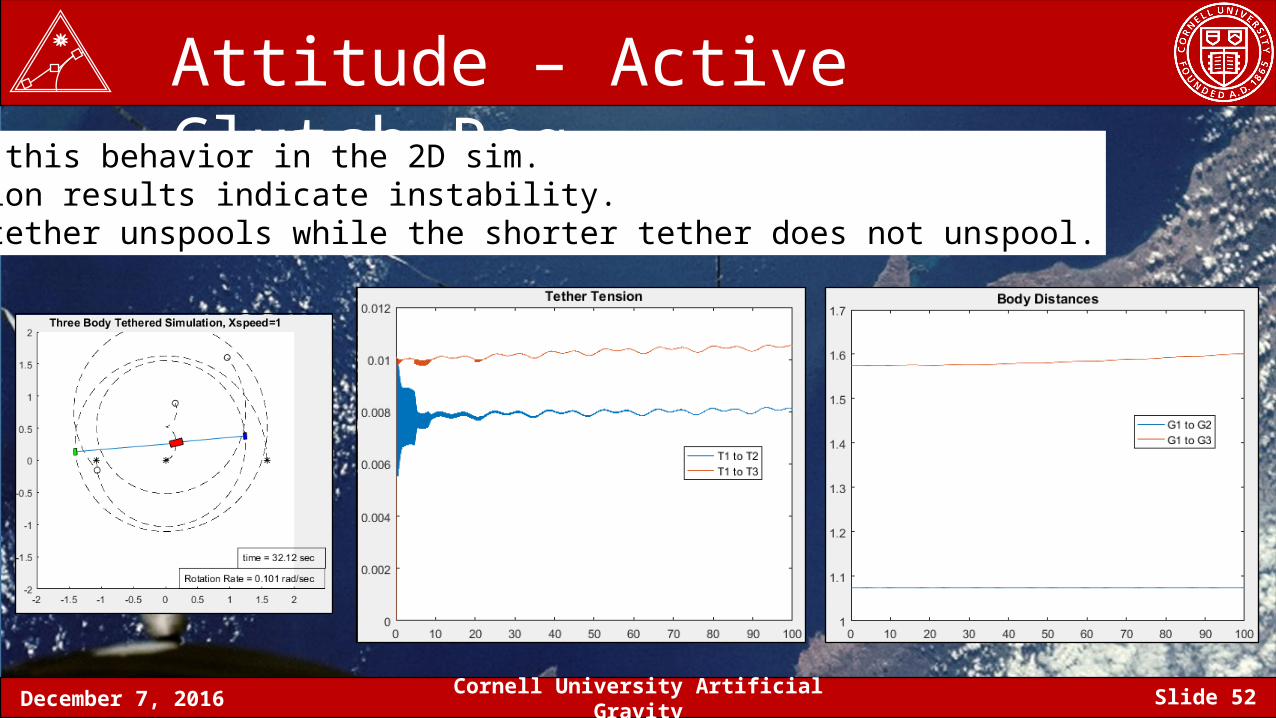
Attitude – Active Clutch ReqA passive clutch is not stable for our application.Any small asymmetry in tether lengths will produce even more asymmetry.The longer tether will unspool and the shorter tether will not unspool.
COMM1M2 M3
r2 r3
𝜔
If the M2 tether is shorter than the M3 tether, then r2 < r3.If r2 < r3, then T2 < T3.If T2 < T3, then the M3 tether unspools at a faster rate than the M2 tether.
December 7, 2016 Cornell University Artificial Gravity Slide 52
Attitude – Active Clutch ReqModeled this behavior in the 2D sim.Simulation results indicate instability.Longer tether unspools while the shorter tether does not unspool.
December 7, 2016 Cornell University Artificial Gravity Slide 53
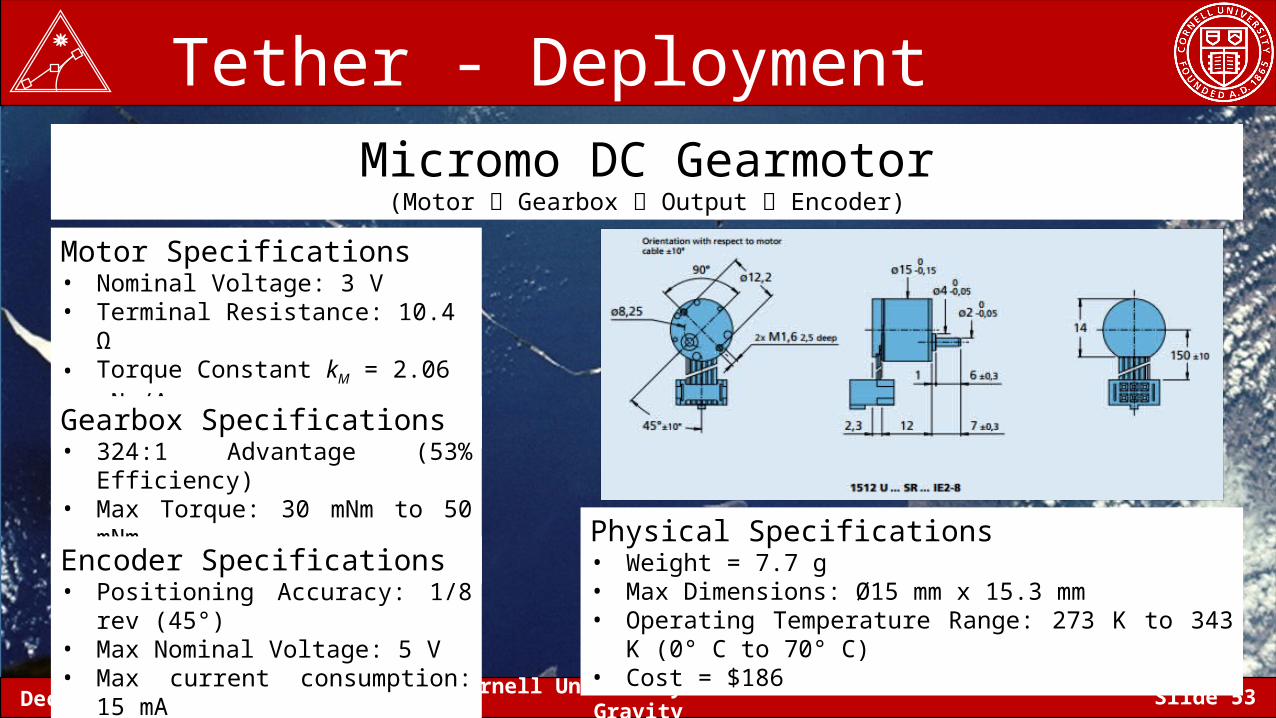
Tether - DeploymentMicromo DC Gearmotor
(Motor Gearbox Output Encoder)
Motor Specifications• Nominal Voltage: 3 V• Terminal Resistance: 10.4 Ω• Torque Constant kM = 2.06 mNm/A• Max Backlash: 4°
Gearbox Specifications• 324:1 Advantage (53% Efficiency)• Max Torque: 30 mNm to 50 mNm• Max RPM: 15 RPM
Encoder Specifications• Positioning Accuracy: 1/8 rev (45°)• Max Nominal Voltage: 5 V• Max current consumption: 15 mA
Physical Specifications• Weight = 7.7 g• Max Dimensions: Ø15 mm x 15.3 mm• Operating Temperature Range: 273 K to 343 K (0° C to 70° C)• Cost = $186
December 7, 2016 Cornell University Artificial Gravity Slide 54
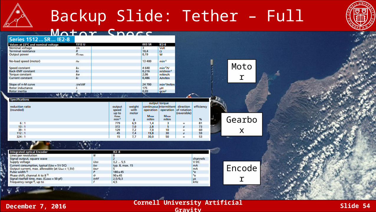
Backup Slide: Tether – Full Motor Specs
Motor
Gearbox
Encoder
December 7, 2016 Cornell University Artificial Gravity Slide 55
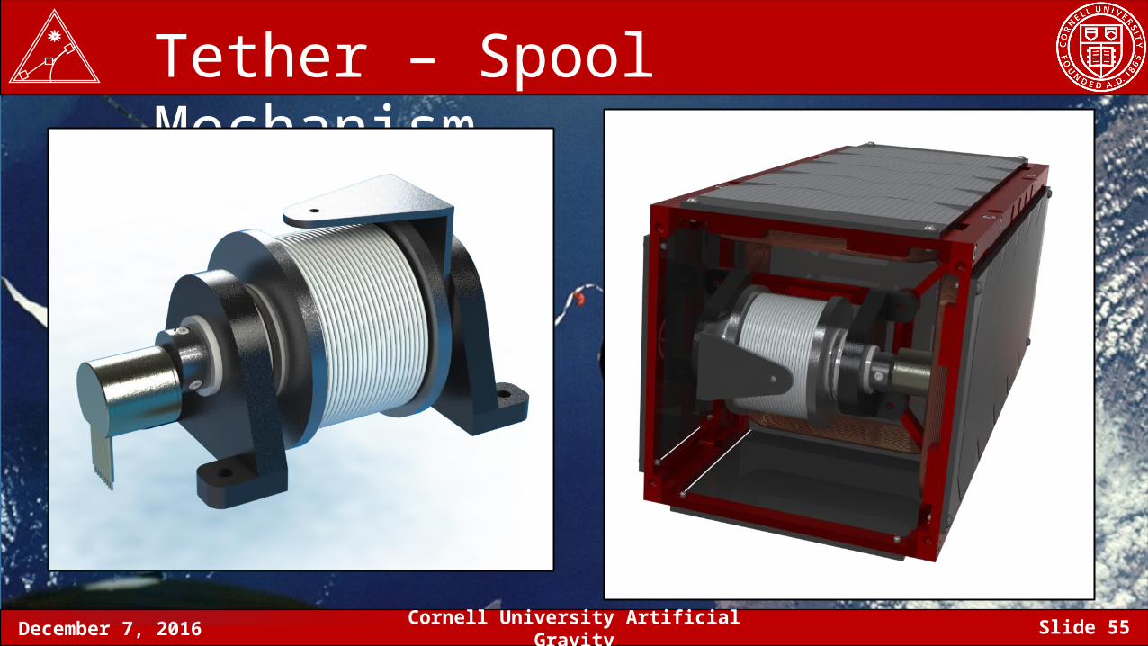
Tether – Spool Mechanism
December 7, 2016 Cornell University Artificial Gravity Slide 56
Tether – Spool Mechanism
1
2
3
4
5
6
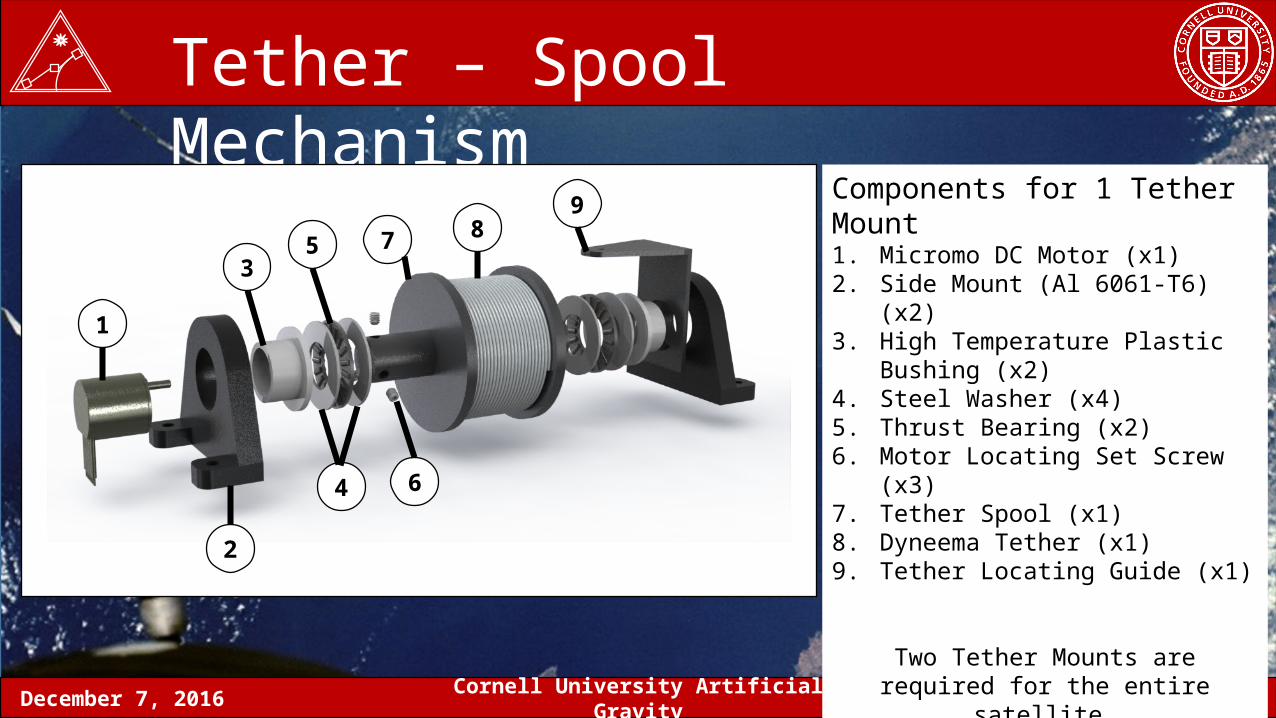
79 Components for 1 Tether Mount
1. Micromo DC Motor (x1)2. Side Mount (Al 6061-T6) (x2)3. High Temperature Plastic Bushing (x2)4. Steel Washer (x4)5. Thrust Bearing (x2)6. Motor Locating Set Screw (x3)7. Tether Spool (x1)8. Dyneema Tether (x1)9. Tether Locating Guide (x1)
Two Tether Mounts are required for the entire satellite.
8
December 7, 2016 Cornell University Artificial Gravity Slide 57
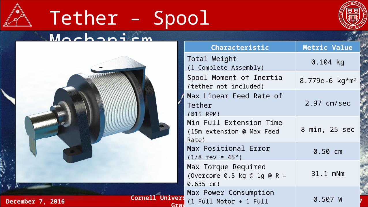
Tether – Spool Mechanism Characteristic Metric Value
Total Weight(1 Complete Assembly) 0.104 kg
Spool Moment of Inertia(tether not included) 8.779e-6 kg*m2
Max Linear Feed Rate of Tether(@15 RPM) 2.97 cm/sec
Min Full Extension Time(15m extension @ Max Feed Rate) 8 min, 25 sec
Max Positional Error(1/8 rev = 45°) 0.50 cm
Max Torque Required(Overcome 0.5 kg @ 1g @ R = 0.635 cm) 31.1 mNm
Max Power Consumption(1 Full Motor + 1 Full Encoder) 0.507 W
December 7, 2016 Cornell University Artificial Gravity Slide 58
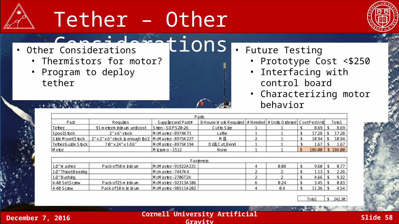
Tether – Other Considerations• Other Considerations
• Thermistors for motor?• Program to deploy tether
• Future Testing• Prototype Cost <$250• Interfacing with control board• Characterizing motor behavior
Part Requires Supplier and Part # In House Work Required # Needed # Units Ordered Cost Per Unit TotalTether 91 meter minimum unit cost Stren - SOPS20-26 Cut to Size 1 1 8.69$ 8.69$ Spool Stock 2" x 6" stock McMaster - 8974K71 Lathe 1 1 17.28$ 17.28$ Side Mount Stock 2" x 2" x 6" stock is enough fpr 2 McMaster - 8975K237 Mill 2 1 10.94$ 10.94$ Tether Guide Stock 7/8" x 24" x 1/16" McMaster - 8975K194 Drill, Cut, Bend 1 1 1.67$ 1.67$ Motor Micromo - 1512 None 1 1 186.00$ 186.00$
1/2" Washer Pack of 50 minimum McMaster - 91922A231 4 0.08 9.60$ 0.77$ 1/2" Thrust Bearing Mcmaster - 7447K4 2 2 1.13$ 2.26$ 1/2" Bushing McMaster - 2706T24 2 2 4.66$ 9.32$ 4-40 Set Screw Pack of 25 minimum McMaster - 92313A106 6 0.24 3.45$ 0.83$ 4-40 Screw Pack of 10 mimimum McMaster - 98511A202 4 0.4 11.36$ 4.54$
Total 242.30$
Fasteners
Parts
December 7, 2016 Cornell University Artificial Gravity Slide 59
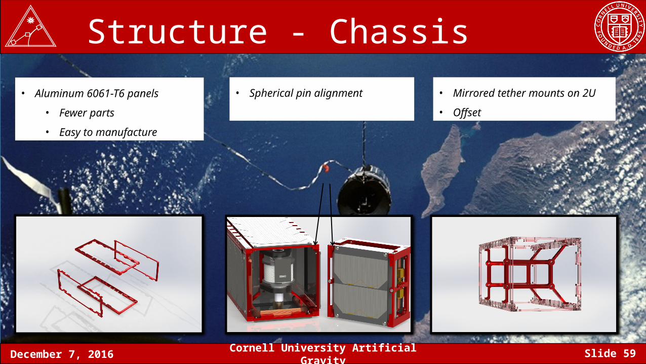
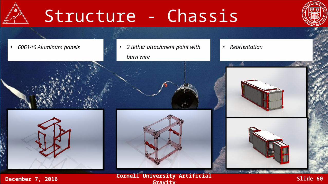
Structure - Chassis• Spherical pin alignment • Mirrored tether mounts on 2U
• Offset
• Aluminum 6061-T6 panels
• Fewer parts
• Easy to manufacture
December 7, 2016 Cornell University Artificial Gravity Slide 60
Structure - Chassis• 2 tether attachment point with burn
wire
• Reorientation• 6061-t6 Aluminum panels
December 7, 2016 Cornell University Artificial Gravity Slide 61
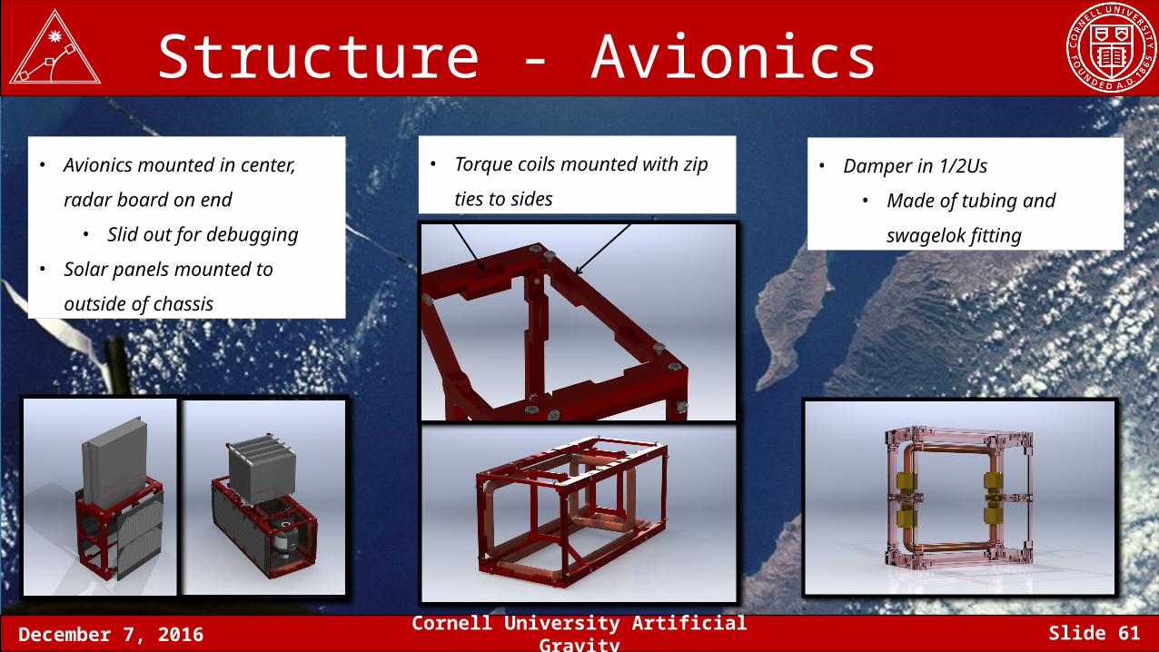
Structure - Avionics• Torque coils mounted with zip ties
to sides
• Damper in 1/2Us
• Made of tubing and
swagelok fitting
• Avionics mounted in center, radar
board on end
• Slid out for debugging
• Solar panels mounted to outside of
chassis
December 7, 2016 Cornell University Artificial Gravity Slide 62
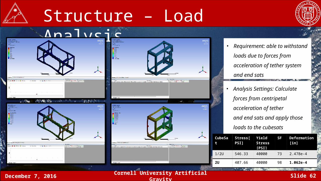
Structure – Load Analysis• Requirement: able to withstand
loads due to forces from
acceleration of tether system and
end sats
• Analysis Settings: Calculate forces
from centripetal acceleration of
tether and end sats and apply
those loads to the cubesats
individually = 0.38g
CubeSat Stress[PSI] Yield Stress [PSI]
SF Deformation [in]
1/2U 546.33 40000 73 2.478e-4
2U 407.66 40000 98 1.062e-4
December 7, 2016 Cornell University Artificial Gravity Slide 63
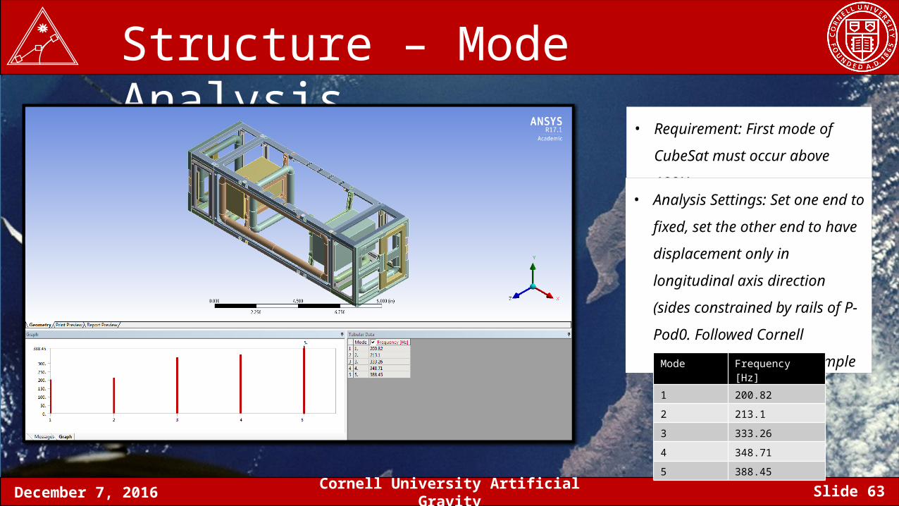
Structure – Mode Analysis• Requirement: First mode of
CubeSat must occur above 100Hz
• Analysis Settings: Set one end to
fixed, set the other end to have
displacement only in longitudinal
axis direction (sides constrained by
rails of P-Pod0. Followed Cornell
University Confluence Example
Mode Frequency [Hz]
1 200.82
2 213.1
3 333.26
4 348.71
5 388.45
December 7, 2016 Cornell University Artificial Gravity Slide 64
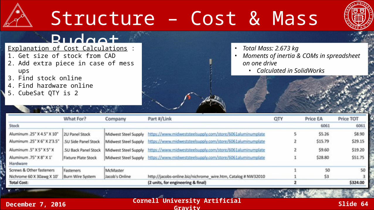
Structure – Cost & Mass BudgetExplanation of Cost Calculations :1. Get size of stock from CAD 2. Add extra piece in case of mess ups 3. Find stock online 4. Find hardware online 5. CubeSat QTY is 2
• Total Mass: 2.673 kg• Moments of inertia & COMs in spreadsheet on
one drive• Calculated in SolidWorks
December 7, 2016 Cornell University Artificial Gravity Slide 65
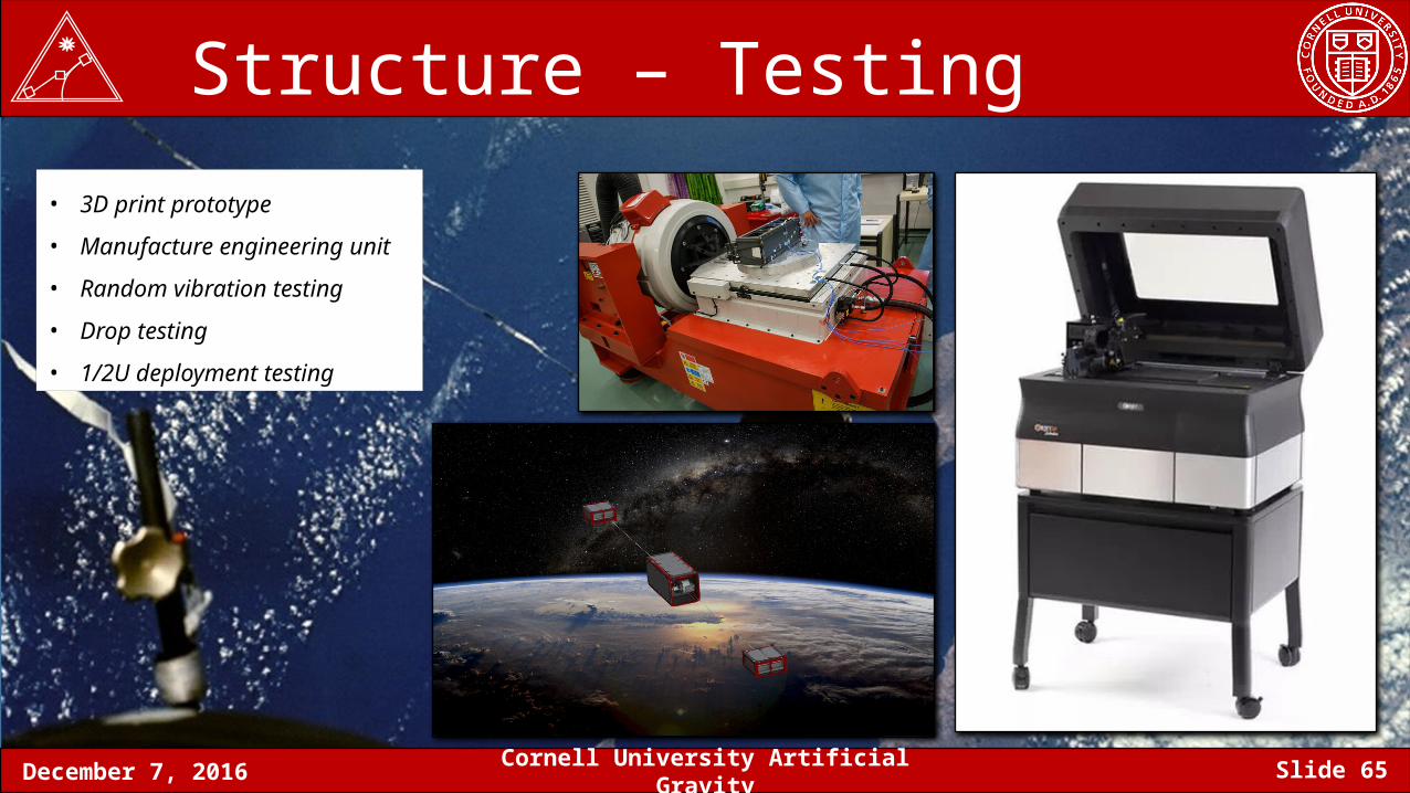
Structure – Testing• 3D print prototype
• Manufacture engineering unit
• Random vibration testing
• Drop testing
• 1/2U deployment testing
December 7, 2016 Cornell University Artificial Gravity Slide 66
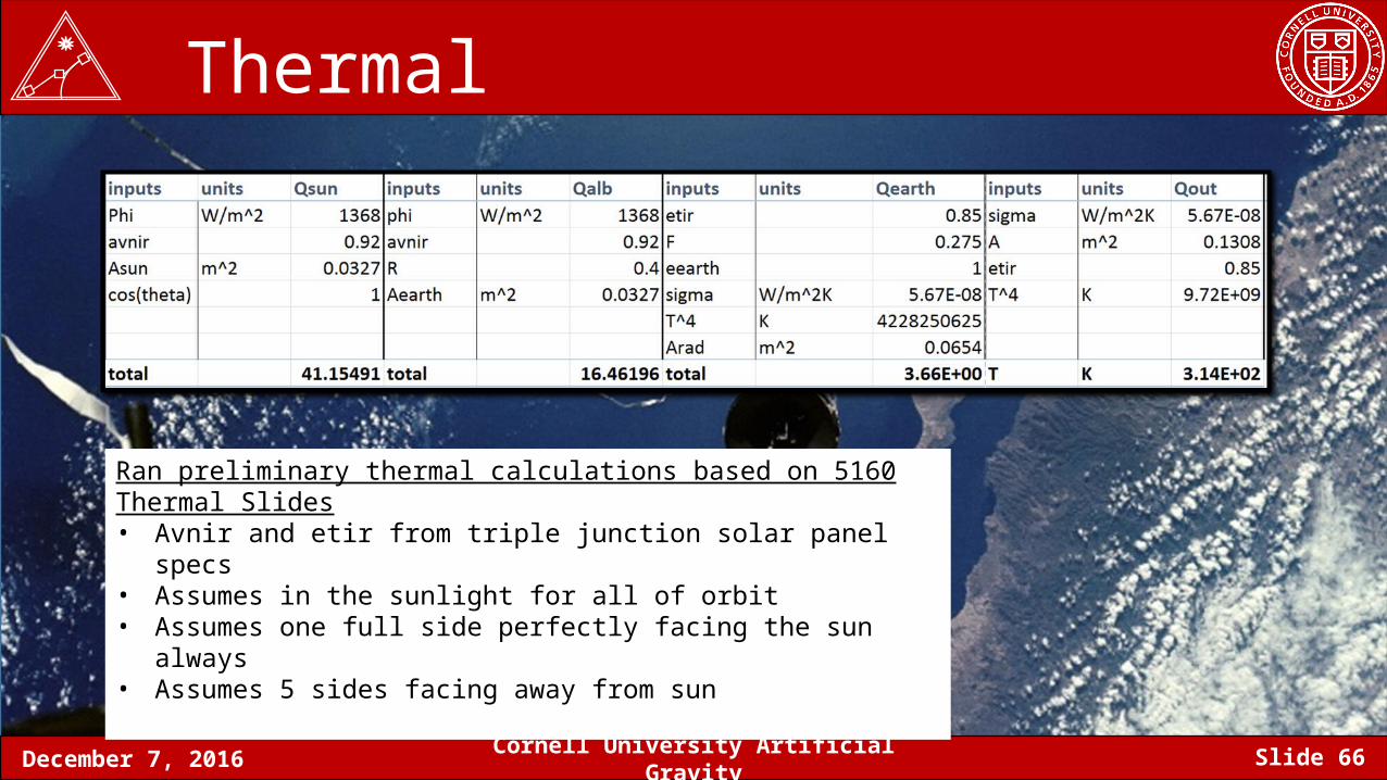
Thermal
Ran preliminary thermal calculations based on 5160 Thermal Slides • Avnir and etir from triple junction solar panel specs • Assumes in the sunlight for all of orbit • Assumes one full side perfectly facing the sun always • Assumes 5 sides facing away from sun
December 7, 2016 Cornell University Artificial Gravity Slide 67
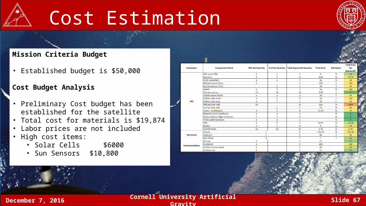
Cost Estimation
Mission Criteria Budget
• Established budget is $50,000
Cost Budget Analysis
• Preliminary Cost budget has been established for the satellite
• Total cost for materials is $19,874• Labor prices are not included• High cost items:
• Solar Cells $6000• Sun Sensors $10,800
December 7, 2016 Cornell University Artificial Gravity Slide 68
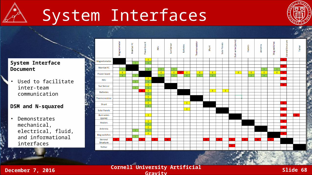
System Interfaces
System Interface Document
• Used to facilitate inter-team communication
DSM and N-squared
• Demonstrates mechanical, electrical, fluid, and informational interfaces
December 7, 2016 Cornell University Artificial Gravity Slide 69
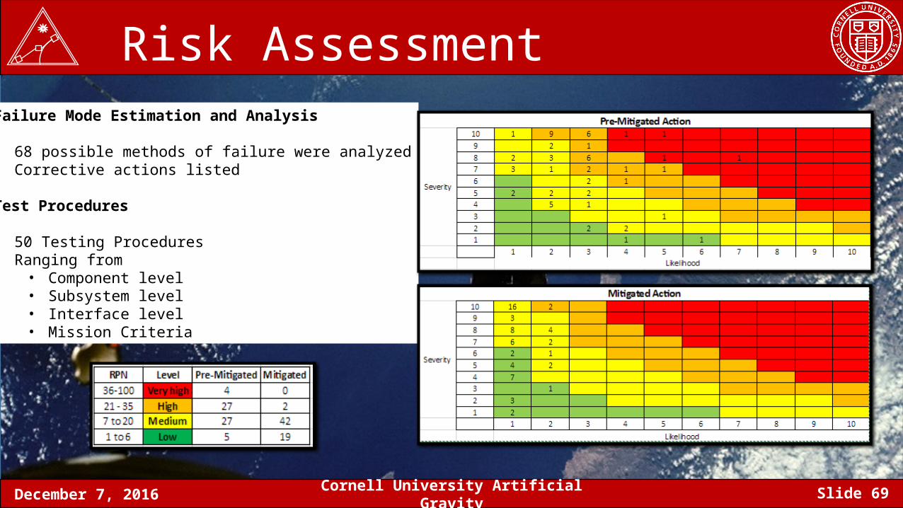
Risk Assessment Failure Mode Estimation and Analysis
• 68 possible methods of failure were analyzed• Corrective actions listed
Test Procedures
• 50 Testing Procedures• Ranging from
• Component level• Subsystem level• Interface level• Mission Criteria
December 7, 2016 Cornell University Artificial Gravity Slide 70
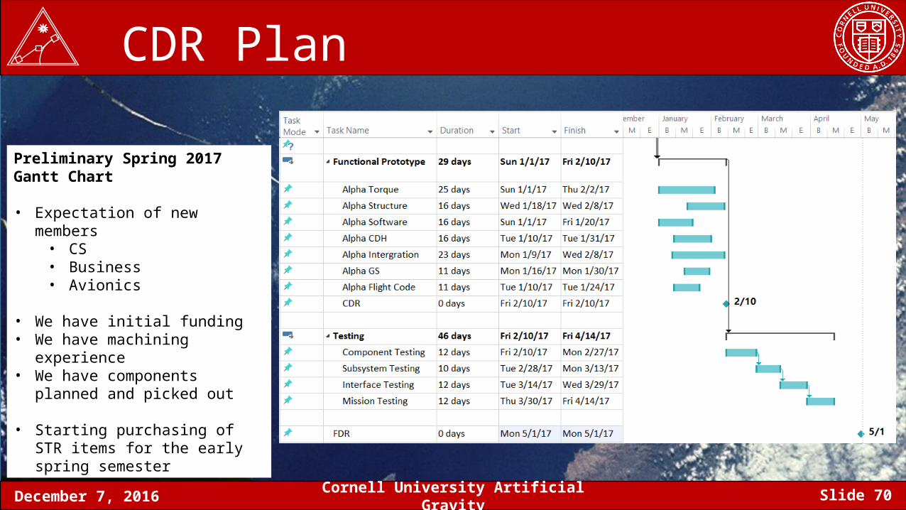
CDR Plan
Preliminary Spring 2017 Gantt Chart
• Expectation of new members• CS• Business• Avionics
• We have initial funding• We have machining experience • We have components planned and
picked out
• Starting purchasing of STR items for the early spring semester
December 7, 2016 Cornell University Artificial Gravity Slide 71
Thank You
Questions?