Multi-Element Lenses - TSUKASA TEC
16
� � � � � � � �� �� � � � � � � ���� ��� ���� � �� Index Interferometer Accessories Appendix Filters Mounts Etalons Polarizers Beamsplitters Ultrafast Components Mirrors Waveplates Lenses Multi-Element Prisms Windows Intro Multi-Element Lenses Multi-Element Overview . . . . . . . . 128 Achromats 425-675nm Cemented Doublets . 132 425-675nm Fast Achromats . . . . . 133 1064/633nm Air-Spaced . . . . . . 134 1064/532nm Air-Spaced . . . . . . 135 Aplanats Visible . . . . . . . . . . . . . . . . . . . . 136 Meniscus Lenses . . . . . . . . . . . . 137 High Energy / UV . . . . . . . . . . . . 138 UV Meniscus . . . . . . . . . . . . . . . 139 UV Focusing Lenses . . . . . . . . . . . . 140 Excimer Laser Focusing Lenses . . . . 140 UV Objective Lenses . . . . . . . . . . . 141 F-Theta Lenses . . . . . . . . . . . . . . . . 142 � �� � � �� � ������������ ������������� ���
Transcript of Multi-Element Lenses - TSUKASA TEC

�����������������
��������������
IndexInterferom
eterA
ccessoriesA
ppendixFilters
Mounts
EtalonsPolarizers
Beamsplitters
Ultrafast
Com
ponentsM
irrorsW
aveplatesLenses
Multi-Elem
entPrism
sW
indows
IntroMulti-Element LensesMulti-Element Overview . . . . . . . . 128
Achromats
425-675nm Cemented Doublets . 132
425-675nm Fast Achromats . . . . . 133
1064/633nm Air-Spaced . . . . . . 134
1064/532nm Air-Spaced . . . . . . 135
Aplanats
Visible . . . . . . . . . . . . . . . . . . . . 136
Meniscus Lenses . . . . . . . . . . . . 137
High Energy / UV. . . . . . . . . . . . 138
UV Meniscus . . . . . . . . . . . . . . . 139
UV Focusing Lenses . . . . . . . . . . . . 140
Excimer Laser Focusing Lenses . . . . 140
UV Objective Lenses . . . . . . . . . . . 141
F-Theta Lenses . . . . . . . . . . . . . . . . 142
�
��
�
�
���
������������
������������� ���
128 Americas (505) 296-9541 | Europe +44 (0) 1624 647000 | Asia +82 (0) 32 673-6114 | Order now at www.cvilaser.com
Win
dow
sPr
ism
sLe
nses
Mul
ti-El
emen
tM
irror
sIn
tro
Beam
split
ters
Pola
rizer
sW
avep
late
sEt
alon
sFi
lters
Ultr
afas
tC
ompo
nent
sIn
terfe
rom
eter
Acc
esso
ries
App
endi
xM
ount
sIn
dex
Figure 2.
�����
���Figure 1.
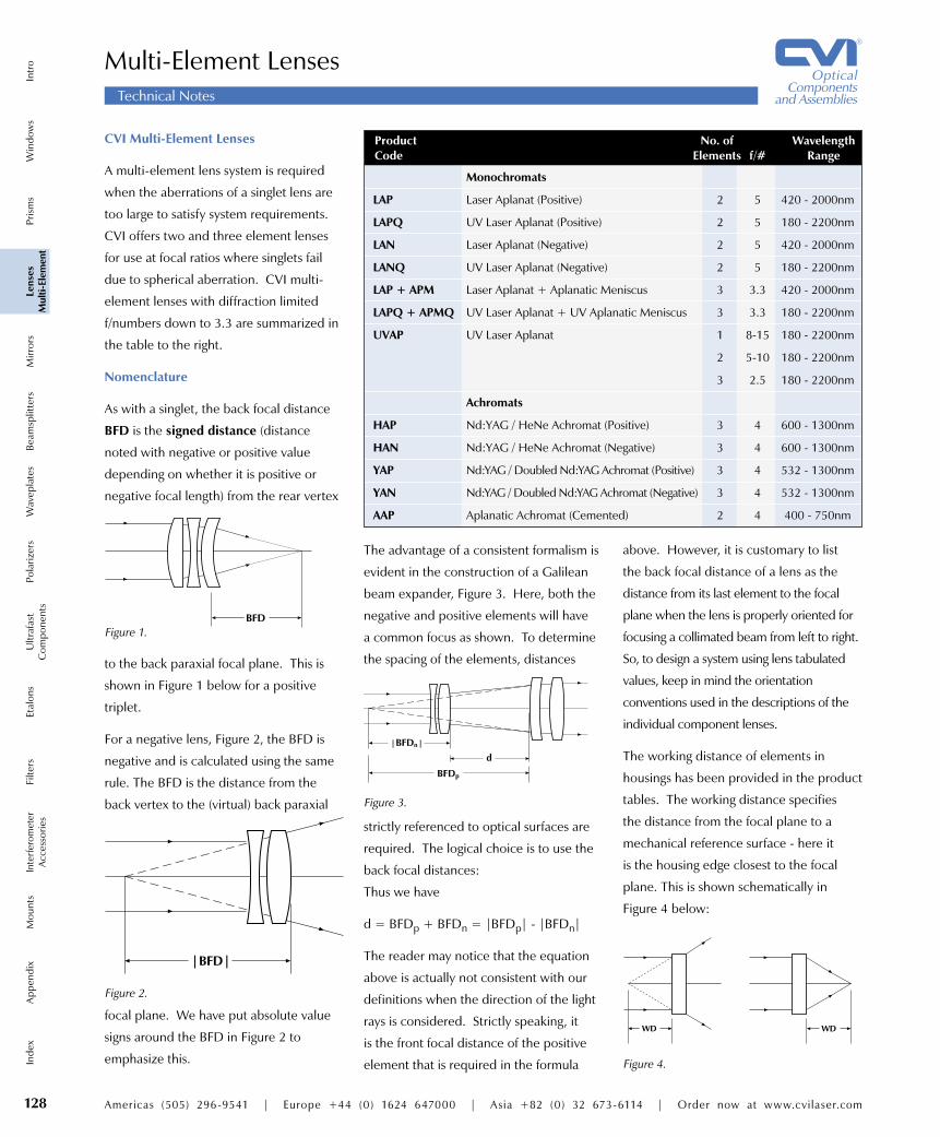
strictly referenced to optical surfaces are
required. The logical choice is to use the
back focal distances:
Thus we have
d = BFDp + BFDn = |BFDp| - |BFDn|
The reader may notice that the equation
above is actually not consistent with our
definitions when the direction of the light
rays is considered. Strictly speaking, it
is the front focal distance of the positive
element that is required in the formula
Multi-Element Lenses
CVI Multi-Element Lenses
A multi-element lens system is required
when the aberrations of a singlet lens are
too large to satisfy system requirements.
CVI offers two and three element lenses
for use at focal ratios where singlets fail
due to spherical aberration. CVI multi-
element lenses with diffraction limited
f/numbers down to 3.3 are summarized in
the table to the right.
Nomenclature
As with a singlet, the back focal distance
BFD is the signed distance (distance
noted with negative or positive value
depending on whether it is positive or
negative focal length) from the rear vertex
to the back paraxial focal plane. This is
shown in Figure 1 below for a positive
triplet.
For a negative lens, Figure 2, the BFD is
negative and is calculated using the same
rule. The BFD is the distance from the
back vertex to the (virtual) back paraxial
above. However, it is customary to list
the back focal distance of a lens as the
distance from its last element to the focal
plane when the lens is properly oriented for
focusing a collimated beam from left to right.
So, to design a system using lens tabulated
values, keep in mind the orientation
conventions used in the descriptions of the
individual component lenses.
The working distance of elements in
housings has been provided in the product
tables. The working distance specifies
the distance from the focal plane to a
mechanical reference surface - here it
is the housing edge closest to the focal
plane. This is shown schematically in
Figure 4 below:
The advantage of a consistent formalism is
evident in the construction of a Galilean
beam expander, Figure 3. Here, both the
negative and positive elements will have
a common focus as shown. To determine
the spacing of the elements, distances
������
����
�
Figure 3.
Figure 4.
����focal plane. We have put absolute value
signs around the BFD in Figure 2 to
emphasize this.
Technical Notes
Product No. of Wavelength Code Elements f/# Range
Monochromats
LAP Laser Aplanat (Positive) 2 5 420 - 2000nm
LAPQ UV Laser Aplanat (Positive) 2 5 180 - 2200nm
LAN Laser Aplanat (Negative) 2 5 420 - 2000nm
LANQ UV Laser Aplanat (Negative) 2 5 180 - 2200nm
LAP + APM Laser Aplanat + Aplanatic Meniscus 3 3.3 420 - 2000nm
LAPQ + APMQ UV Laser Aplanat + UV Aplanatic Meniscus 3 3.3 180 - 2200nm
UVAP UV Laser Aplanat 1 8-15 180 - 2200nm
2 5-10 180 - 2200nm
3 2.5 180 - 2200nm
Achromats
HAP Nd:YAG / HeNe Achromat (Positive) 3 4 600 - 1300nm
HAN Nd:YAG / HeNe Achromat (Negative) 3 4 600 - 1300nm
YAP Nd:YAG / Doubled Nd:YAG Achromat (Positive) 3 4 532 - 1300nm
YAN Nd:YAG / Doubled Nd:YAG Achromat (Negative) 3 4 532 - 1300nm
AAP Aplanatic Achromat (Cemented) 2 4 400 - 750nm

Americas (505) 296-9541 | Europe +44 (0) 1624 647000 | Asia +82 (0) 32 673-6114 | Order now at www.cvilaser.com 129
IndexInterferom
eterA
ccessoriesA
ppendixFilters
Mounts
EtalonsPolarizers
Beamsplitters
Ultrafast
Com
ponentsM
irrorsW
aveplatesLenses
Multi-Elem
entPrism
sW
indows
Intro
Multi-Element Lenses
Aplanat or Achromat?
An Aplanat lens is designed to be free of
two monochromatic (single wavelength)
wavefront errors called Spherical Aberration
and Coma. Spherical Aberration is axially
symmetric and occurs when rays from
a point on the axis passing through the
outer zones of the lens focus at a different
distance from the lens than rays passing
through the central zone. Coma is an off-
axis non-symmetric wavefront distortion
which increases linearly with field angle
or distance from the principal axis. In
combination, these aberrations distort the
transmitted wavefront through the lens and
cause the focal spot to become irregularly
shaped and/or blurred.
On the other hand, Achromatic lenses are
corrected for Chromatic Aberration with
respect to two wavelengths (normally
blue and red). Chromatic aberration is
produced by dispersion, or the variation
of refractive index with wavelength,
and causes different wavelengths to
have different focal points. Using
separate materials like crown glass
and flint glass for the converging and
diverging lens elements, the dispersion
of each can be compensated for by
the other thereby minimizing the total
effect. In photography and precision
micromachining, it is often crucial that the
secondary spectrum or a third wavelength
be color-corrected in addition to the blue
(F-line) and red (C-line).
Neither crown nor flint glasses transmit
well below 420nm so other materials are
required for applications using broadband
or multi-wavelength UV sources. there are
few options available to optical designers,
due to limitations in UV transmitting
materials. Existing designs use fused silica
glass for the positive element, and either
UV grade calcium fluoride or lithium
fluoride for the negative element. An UV
achromat comprised of either of these
material combinations can be optimized
for a 200nm bandwidth centered around
300nm or 350nm depending on the
application requirements.
���������������
���������
���������������
�����������������������������������������������
���������������
������������
���������������
������������
���������������
��������������������
Aplanat Marking Conventions
Positive Systems (Convergent)
The arrow marking on the housing
always points to the collimated light.
Negative Systems (Divergent)
The arrow marking on the housing
always points to the collimated light.
UV achromats are ideally suited to
broadband UV applications including
photometric instrumentation and
fluorescence analysis. They can also be
used as UV focusing lenses in place of
aplanat lenses in certain situations. Most
commercially available UV aplanats are
designed for 248nm. At other wavelengths,
such as the laser diodes at 365nm (I line)
and 405nm (H line) used in lithography
exposure systems, more precise focal
lengths may result from using an achromat
in place of an aplanat which was designed
for a different wavelength.
LAP/LAN Series Laser Aplanats
The LAP/LAN Series Laser Aplanats are
air-spaced doublets designed to produce
minimum focal spot size. An aplanat is
a lens designed to minimize spherical
aberration and coma. The LAP/LAN Series
lenses exhibit essentially diffraction limited
performance over their full f/5 apertures.
Use LAP/LAN doublets when the focal
spot of a monochromatic laser must be
an absolute minimum. Applications
include nonlinear optics experiments,
laser beam expanders and collimators,
interferometers, beam handling systems,
material ablation and cutting systems,
power fiber optic interfacing, and other
applications where lenses are used to
focus collimated beams.
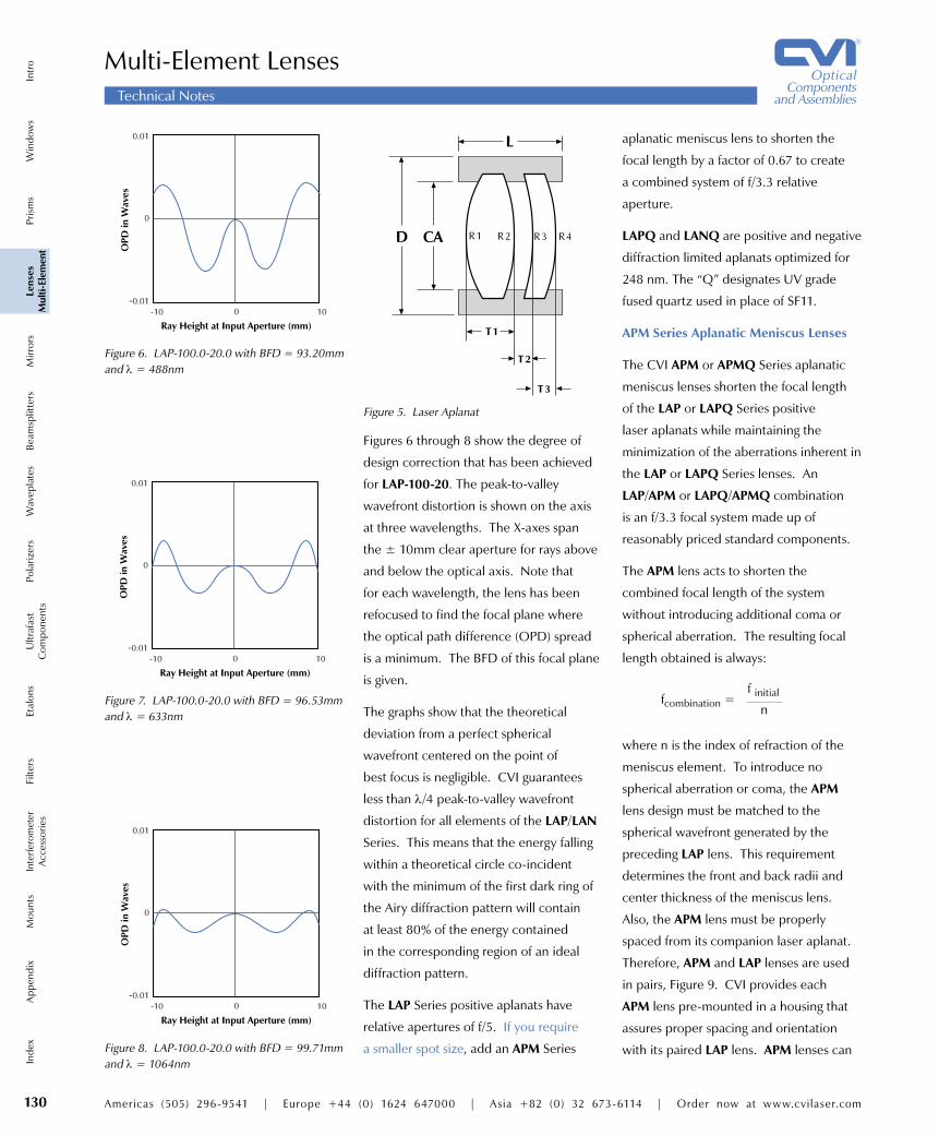
Figure 5 shows the construction of the LAP
Series positive lenses; identical definitions
apply to the LAN Series negative lenses.
Both elements are fabricated from SF11
glass and are antireflection coated with
hard, damage resistant coatings. Lens
design prescriptions are available in many
of the commercially available optical
design software packages to facilitate
computer analysis, such as ZEMAX.
Technical Notes
130 Americas (505) 296-9541 | Europe +44 (0) 1624 647000 | Asia +82 (0) 32 673-6114 | Order now at www.cvilaser.com
Win
dow
sPr
ism
sLe
nses
Mul
ti-El
emen
tM
irror
sIn
tro
Beam
split
ters
Pola
rizer
sW
avep
late
sEt
alon
sFi
lters
Ultr
afas
tC
ompo
nent
sIn
terfe
rom
eter
Acc
esso
ries
App
endi
xM
ount
sIn
dex
aplanatic meniscus lens to shorten the
focal length by a factor of 0.67 to create
a combined system of f/3.3 relative
aperture.
LAPQ and LANQ are positive and negative
diffraction limited aplanats optimized for
248 nm. The “Q” designates UV grade
fused quartz used in place of SF11.
APM Series Aplanatic Meniscus Lenses
The CVI APM or APMQ Series aplanatic
meniscus lenses shorten the focal length
of the LAP or LAPQ Series positive
laser aplanats while maintaining the
minimization of the aberrations inherent in
the LAP or LAPQ Series lenses. An
LAP/APM or LAPQ/APMQ combination
is an f/3.3 focal system made up of
reasonably priced standard components.
The APM lens acts to shorten the
combined focal length of the system
without introducing additional coma or
spherical aberration. The resulting focal
length obtained is always:
where n is the index of refraction of the
meniscus element. To introduce no
spherical aberration or coma, the APM
lens design must be matched to the
spherical wavefront generated by the
preceding LAP lens. This requirement
determines the front and back radii and
center thickness of the meniscus lens.
Also, the APM lens must be properly
spaced from its companion laser aplanat.
Therefore, APM and LAP lenses are used
in pairs, Figure 9. CVI provides each
APM lens pre-mounted in a housing that
assures proper spacing and orientation
with its paired LAP lens. APM lenses can
Figures 6 through 8 show the degree of
design correction that has been achieved
for LAP-100-20. The peak-to-valley
wavefront distortion is shown on the axis
at three wavelengths. The X-axes span
the ± 10mm clear aperture for rays above
and below the optical axis. Note that
for each wavelength, the lens has been
refocused to find the focal plane where
the optical path difference (OPD) spread
is a minimum. The BFD of this focal plane
is given.
The graphs show that the theoretical
deviation from a perfect spherical
wavefront centered on the point of
best focus is negligible. CVI guarantees
less than λ/4 peak-to-valley wavefront
distortion for all elements of the LAP/LAN
Series. This means that the energy falling
within a theoretical circle co-incident
with the minimum of the first dark ring of
the Airy diffraction pattern will contain
at least 80% of the energy contained
in the corresponding region of an ideal
diffraction pattern.
The LAP Series positive aplanats have
relative apertures of f/5. If you require
a smaller spot size, add an APM Series
fcombination =f initial
n
Figure 8. LAP-100.0-20.0 with BFD = 99.71mm and λ = 1064nm
�
����
�������� � ��
���
�����
����
���������������������������������
Figure 7. LAP-100.0-20.0 with BFD = 96.53mm and λ = 633nm
�
����
�������� � ��
���
�����
����
���������������������������������
Figure 6. LAP-100.0-20.0 with BFD = 93.20mm and λ = 488nm
�
����
�������� � ��
���
�����
����
���������������������������������
�
� ��
��
��
��
�� �� �� ��
Figure 5. Laser Aplanat
Multi-Element LensesTechnical Notes

Americas (505) 296-9541 | Europe +44 (0) 1624 647000 | Asia +82 (0) 32 673-6114 | Order now at www.cvilaser.com 131
IndexInterferom
eterA
ccessoriesA
ppendixFilters
Mounts
EtalonsPolarizers
Beamsplitters
Ultrafast
Com
ponentsM
irrorsW
aveplatesLenses
Multi-Elem
entPrism
sW
indows
Intro
they are air-spaced, they can be used in
high power YAG applications. The coatings
are designed to give reflection losses of
less than 0.5% per surface at both 1064nm
and 633nm. Uncoated reflections can
be as much as 4% per surface on BK7
elements and 8% per surface on SF11
elements.
To compare the performance of these
lenses with that of telescope objectives,
one can ray-trace representative telescopes
consisting of two CVI cemented aplanats
and two high power achromats. The high
power achromats offer better wavefront
quality and achromatization at two useful
laser wavelengths. The inner surfaces are
air-spaced and coated with high efficiency
anti-reflection coatings and are suitable for
high power applications that would cause
telescope objectives to fail.
YAG/Doubled YAG Achromats
These lenses are similar to the HAP/HAN
Series except they are achromatized for
1064nm and 532nm. They are air-spaced
and all surfaces are coated with double-V
AR coatings that have anti-reflection of
less than 0.6% per surfaceat both 1064nm
and 532nm. These lenses can be used to
focus YAG and doubled YAG beams simul-
taneously or to form a beam expander that
is concurrently collimated for YAG and
doubled YAG.
A cross section of the YAP-100.0-20.0 is
shown in Figure 11. Figure 12 shows the
OPD fans for this lens at the best common
focus. Both wavelengths are theoretically
less than λ/20 peak-to-valley transmitted
wavefront distortion. These lenses are
diffraction limited at 1064nm and 532nm.
be ordered with their companion laser
aplanats or separately. This gives you the
ability to change the focal length of an
existing system at a later time.
UVAP UV and Excimer Laser
Focusing Lenses
CVI designed the UVAP Series to
focus large aperture excimer beams
and for general purpose ultraviolet
focusing applications. The UVAP
Series has optimum correction of
spherical aberration and coma in a lens
transmitting to 200nm. Choose lenses
from this series whenever your application
requires ultraviolet diffraction limited
performance at modest f/numbers.
Lenses from the UVAP Series can satisfy
many requirements in photoablation,
microlithography, and image relay
applications without the need for
expensive custom designs.
YAG/HeNe Achromats
These air-spaced triplets have the same
focal length at 1064nm and 633nm. They
can be used to focus a YAG beam and
HeNe beam to align to the same point.
They can also be used to form beam
expanders that collimate YAG and HeNe
beams at the same lens spacing.
These lenses are corrected for spherical
aberration at 1064nm and 633nm and for
coma at 1064nm (see Figure 10). Because
Figure 10. HAP-100.0-20.0 OPD fan
�
����
�������� � ��
������
���
�����
����
���������������������������������
�������
�
����
�������� � ��
���
�����
����
���������������������������������
�������
������
Figure 12. YAP-100.0-20.0 OPD fan
Figure 11. YAP-100.0-20.0
������
Figure 9. The LAP lens is inserted into the housing of the APM companion meniscus lens.
Multi-Element LensesTechnical Notes

132 Americas (505) 296-9541 | Europe +44 (0) 1624 647000 | Asia +82 (0) 32 673-6114 | Order now at www.cvilaser.com
Win
dow
sPr
ism
sLe
nses
Mul
ti-El
emen
tM
irror
sIn
tro
Beam
split
ters
Pola
rizer
sW
avep
late
sEt
alon
sFi
lters
Ultr
afas
tC
ompo
nent
sIn
terfe
rom
eter
Acc
esso
ries
App
endi
xM
ount
sIn
dex
Focal lengths from 25mm to 2000mm CVI low loss 425-675nm BBAR
coating included l 46-49 See HAP/HAN or YAP/YAN for
1064nm air-spaced designs l 134
AAP, AAN
Substrate Material BK7 and SF2, SF6, or SF11 glass
Surface Quality 40-20 per MIL-PRF-13830B
Diameter Tolerance ± 0.25mm
Clear Aperture Central 85% of diameter
Field of view 4°
Design Wavelength 500-620nm Visible
Transmitted Wavefront Distortion λ/2 p-v at 633nm
�
AAP - Positive Cemented Doublet Achromat
�
AAN - Negative Cemented Doublet Achromat
425-675nm Cemented Doublet Achromats
�����
����
���
�����
��������� ��� ��� ��� ��� ���
���������������
����
�����
������
�
��������������
Chromatic focal shift vs. wavelength for AAP-100.0-25.4 doublet achromat.
AAPAAN
425-675nm Cemented Doublet Achromats Focal Diameter Part Number Length D f/D
Positive Cemented Doublet Achromats
AAP-25.0-6.35 25.0 6.35 4.6
AAP-30.0-6.35 30.0 6.35 5.6
AAP-50.0-12.7 50.0 12.7 4.6
AAP-75.0-12.7 75.0 12.7 6.9
AAP-100.0-25.4 100.0 25.4 4.6
AAP-125.0-25.4 125.0 25.4 5.8
AAP-150.0-25.4 150.0 25.4 6.9
AAP-200.0-25.4 200.0 25.4 9.3
AAP-200.0-50.8 200.0 50.8 4.6
AAP-250.0-25.4 250.0 25.4 11.6
AAP-250.0-50.8 250.0 50.8 5.8
AAP-300.0-25.4 300.0 25.4 13.9
AAP-300.0-50.8 300.0 50.8 6.9
AAP-300.0-76.2 300.0 76.2 4.6
AAP-500.0-25.4 500.0 25.4 23.2
AAP-500.0-50.8 500.0 50.8 11.6
AAP-500.0-76.2 500.0 76.2 7.7
AAP-500.0-101.6 500.0 101.6 5.8
AAP-1000.0-25.4 1000.0 25.4 46.3
AAP-1000.0-50.8 1000.0 50.8 23.2
AAP-1000.0-76.2 1000.0 76.2 15.4
AAP-1000.0-101.6 1000.0 101.6 11.6
AAP-1500.0-25.4 1500.0 25.4 69.5
AAP-1500.0-50.8 1500.0 50.8 34.7
AAP-2000.0-25.4 2000.0 25.4 92.6
AAP-2000.0-50.8 2000.0 50.8 46.3
Negative Cemented Doublet Achromats
AAN-25.0-6.35 -25.0 6.35 3.9
AAN-30.0-6.35 -30.0 6.35 4.7
AAN-50.0-12.7 -50.0 12.7 3.9
AAN-75.0-12.7 -75.0 12.7 5.9Unless otherwise noted, all measurements in mm.
Antireflection Coating Ravg ≤ 0.5%, 425-675nm
Damage Threshold 500mJ/cm2, 20ns, 20Hz; 100W/cm2, CW at 515nm

Americas (505) 296-9541 | Europe +44 (0) 1624 647000 | Asia +82 (0) 32 673-6114 | Order now at www.cvilaser.com 133
IndexInterferom
eterA
ccessoriesA
ppendixFilters
Mounts
EtalonsPolarizers
Beamsplitters
Ultrafast
Com
ponentsM
irrorsW
aveplatesLenses
Multi-Elem
entPrism
sW
indows
Intro
���������������
�������������
��
���
�������������
Application in fiber optic couplings Low f/# aplanatic achromat
positive lens system Infinite conjugate design CVI low loss 425-675nm
BBAR coating included l 46-49
FAP 425-675nm Fast Achromats
Substrate Material BK7 and SF2 glass
Design Wavelengths Visible (500-620nm)
Focal Length Tolerance ± 0.5%
Housing Black anodized aluminum barrel
Housing Tolerance ± 0.005”
�����
����
���
�����
��������� ��� ��� ��� ��� ���
���������������
����
�����
������
�
��������������
Chromatic focal shift vs. wavelength for FAP-100.0-46.0 fast achromat.
Product Code
Focal Length in mm
Clear Aperture Diameter in mm
Wavelength Range of AR Coating in nm
How To Order 425-67525.050.0FAP
Two air-spaced doublets make this
achromat ideal for fiber optic coupling
and similar applications where a very low
f/# is required. This fast achromat design
also minimizes spherical aberration and
coma. Vent holes can be placed in the
barrel between the doublets for vacuum
applications. Contact CVI for pricing and
delivery of custom features.
FAP
425-675nm Fast Achromats Focal Housing Housing BBAR Part Number Length f/# NA BFL WD Diameter Length Coating (nm) FAP-25.0-15.0-425-675 25.0 1.7 0.30 15.0 14.4 28.6 25.4 425-675
FAP-50.0-25.0-425-675 50.0 2.0 0.25 40.5 39.1 38.1 25.4 425-675
FAP-100.0-46.0-425-675 100.0 2.2 0.23 83.5 81.1 63.5 38.1 425-675
FAP-150.0-60.0-425-675 150.0 2.5 0.20 130.6 128.2 76.2 44.4 425-675Unless otherwise noted, all measurements in mm.
Antireflection Coating Ravg ≤ 0.5%, 425-675nm
Transmitted Wavefront Distortion λ/2 p-v at 633nm
Damage Threshold 500mJ/cm2, 20ns, 20Hz; 100W/cm2, CW at 1064nm

134 Americas (505) 296-9541 | Europe +44 (0) 1624 647000 | Asia +82 (0) 32 673-6114 | Order now at www.cvilaser.com
Win
dow
sPr
ism
sLe
nses
Mul
ti-El
emen
tM
irror
sIn
tro
Beam
split
ters
Pola
rizer
sW
avep
late
sEt
alon
sFi
lters
Ultr
afas
tC
ompo
nent
sIn
terfe
rom
eter
Acc
esso
ries
App
endi
xM
ount
sIn
dex
Dual wavelength beamsteering applications
Same focal length for 1064nm and 633nm
Excellent achromatic performance for Ti:Sapphire at 800nm
Air-spaced design for high energy laser applications
All surfaces AR coated for both 1064nm and 633nm
Substrate Material BK7 and SF11 glass
Surface Quality 40-20 per MIL-PRF-13830B
Housing Tolerance ± 0.005”
HAP, HAN
HAP Series Positive Laser Achromats
�
�����
���
HAN Series Negative Laser Achromats
����
��
�
��
1064/633nm Air-Spaced Laser Achromats
Chromatic focal shift vs. wavelength for HAN-50.0-10.0 1064/633 achromat.
�����
����
���
�����
��������� ��� ��� ��� ��� ����
���������������
����
�����
������
�
�������������
These air-spaced triplets have the same focal length at 1064nm and 633nm. They can be used to focus a Nd:YAG beam and HeNe beam to align to the same point. They can also be used to form beam expanders that collimate Nd:YAG and HeNe beams at the same lens spacing.
These lenses are corrected for spherical aberration at 1064nm and 633nm and
for coma at 1064nm. Because they are air-spaced, they can be used in high power Nd:YAG applications. The coatings are designed to give reflection losses of less than 0.5% per surface at 1064nm and 633nm.
To compare the performance of these lenses with that of telescope objectives, one can ray-trace representative telescopes consisting of two CVI cemented aplanats and two high power achromats. The high power achromats offer high wavefront quality and achromatization at two useful laser wavelengths. The inner surfaces are air-spaced and coated with high efficiency anti-reflection coatings and are suitable for high power applications that would cause telescope objectives to fail.
HAPHAN
1064/633nm Air-Spaced Laser Achromats Clear Working Back Focal Outside Focal Aperture Distance Distance Diameter Length Part Number Length CA WD BFD D L
Positive Achromats
HAP-10.0-2.0 10.0 2.0 7.0 7.7 12.7 4.3
HAP-15.0-3.0 15.0 3.0 10.0 11.7 12.7 11.4
HAP-25.0-5.0 25.0 5.0 20.6 21.6 19.0 8.0
HAP-50.0-10.0 50.0 10.0 41.0 45.7 19.0 11.8
HAP-75.0-15.0 75.0 15.0 64.0 68.7 25.4 14.7
HAP-100.0-20.0 100.0 20.0 89.0 93.5 28.6 14.4
HAP-125.0-25.0 125.0 25.0 112.0 119.4 31.8 19.0
HAP-150.0-30.0 150.0 30.0 135.0 143.1 40.6 19.0
HAP-200.0-40.0 200.0 40.0 184.0 190.6 50.8 22.4
HAP-250.0-50.0 250.0 50.0 233.0 239.6 61.3 24.7
Negative Achromats
HAN-10.0-2.0 -10.0 2.0 12.0 -11.4 12.7 7.4
HAN-15.0-3.0 -15.0 3.0 18.0 -17.1 12.7 8.1
HAN-25.0-5.0 -25.0 5.0 30.0 -30.5 14.0 12.7
HAN-50.0-10.0 -50.0 10.0 57.0 -54.1 19.0 16.9Unless otherwise noted, all measurements in mm.
Antireflection Coating R ≤ 0.5% per surface at 1064nm and 633nm
Transmitted Wavefront Distortion λ/2 p-v over 85% of CA at 633nm
Damage Threshold 4J/cm2, 20ns, 20Hz at 1064nm

Americas (505) 296-9541 | Europe +44 (0) 1624 647000 | Asia +82 (0) 32 673-6114 | Order now at www.cvilaser.com 135
IndexInterferom
eterA
ccessoriesA
ppendixFilters
Mounts
EtalonsPolarizers
Beamsplitters
Ultrafast
Com
ponentsM
irrorsW
aveplatesLenses
Multi-Elem
entPrism
sW
indows
IntroYAP, YAN 1064/532nm Air-Spaced Laser Achromats
Dual wavelength beamsteering applications
Same focal length for 1064nm and 532nm
Air-spaced design for high energy laser applications
All surfaces AR coated for both 1064nm and 532nm
Substrate Material BK7 and SF11 glass
Surface Quality 40-20 per MIL-PRF-13830B
Housing Tolerance ± 0.005”
YAP Series Positive Laser Achromats
�
�����
���
YAN Series Negative Laser Achromats
����
��
�
��
Chromatic focal shift vs. wavelength for YAP-100.0-20.0 1064/532 achromat.
�����
�����
���
������
��������� ��� ��� ��� ��� ����
���������������
����
�����
������
�
��������������
These lenses are achromatized for
1064nm and 532nm. They are air-spaced
and all surfaces are coated with double-
V AR coatings that have anti-reflection
of less than 0.6% at both 1064nm and
532nm. These lenses can be used to
focus Nd:YAG and doubled Nd:YAG
beams simultaneously or to form a beam
expander that is concurrently collimated
for Nd:YAG and doubled Nd:YAG.
OPD shows the fans for this lens at the
best common focus. Both wavelengths are
theoretically less than λ/20 peak-to-valley
transmitted wavefront distortion.
YAPYAN
1064/532nm Air-Spaced Laser Achromats Clear Working Back Focal Outside Focal Aperture Distance Distance Diameter Length Part Number Length CA WD BFD D L
Positive Achromats
YAP-10.0-2.0 10.0 2.0 6.0 7.5 12.7 4.3
YAP-15.0-3.0 15.0 3.0 10.0 13.6 12.7 11.4
YAP-25.0-5.0 25.0 5.0 21.0 21.7 19.0 7.1
YAP-50.0-10.0 50.0 10.0 41.0 45.6 19.0 11.8
YAP-75.0-15.0 75.0 15.0 65.0 68.9 25.4 14.7
YAP-100.0-20.0 100.0 20.0 89.0 94.2 28.6 14.4
YAP-125.0-25.0 125.0 25.0 111.0 117.7 31.8 19.0
YAP-150.0-30.0 150.0 30.0 136.0 142.4 40.6 19.0
YAP-200.0-40.0 200.0 40.0 184.0 190.6 50.8 22.4
YAP-250.0-50.0 250.0 50.0 233.0 239.1 61.3 22.7
Negative Achromats
YAN-10.0-2.0 -10.0 2.0 12.0 -10.7 12.7 7.4
YAN-15.0-3.0 -15.0 3.0 16.0 -15.0 12.7 8.1
YAN-25.0-5.0 -25.0 5.0 28.0 -26.0 14.0 12.7
YAN-50.0-10.0 -50.0 10.0 55.0 -52.2 19.0 19.3Unless otherwise noted, all measurements in mm.
�
����
�������� � ��
���
�����
����
���������������������������������
�������
������
Antireflection Coating R < 0.3% per surface at 1064nm and
R < 0.6% per surface at 532nm
Transmitted Wavefront Distortion λ/2 p-v over 85% of CA at 633nm
Damage Threshold 4J/cm2, 20ns, 20Hz at 1064nm
136 Americas (505) 296-9541 | Europe +44 (0) 1624 647000 | Asia +82 (0) 32 673-6114 | Order now at www.cvilaser.com
Win
dow
sPr
ism
sLe
nses
Mul
ti-El
emen
tM
irror
sIn
tro
Beam
split
ters
Pola
rizer
sW
avep
late
sEt
alon
sFi
lters
Ultr
afas
tC
ompo
nent
sIn
terfe
rom
eter
Acc
esso
ries
App
endi
xM
ount
sIn
dex
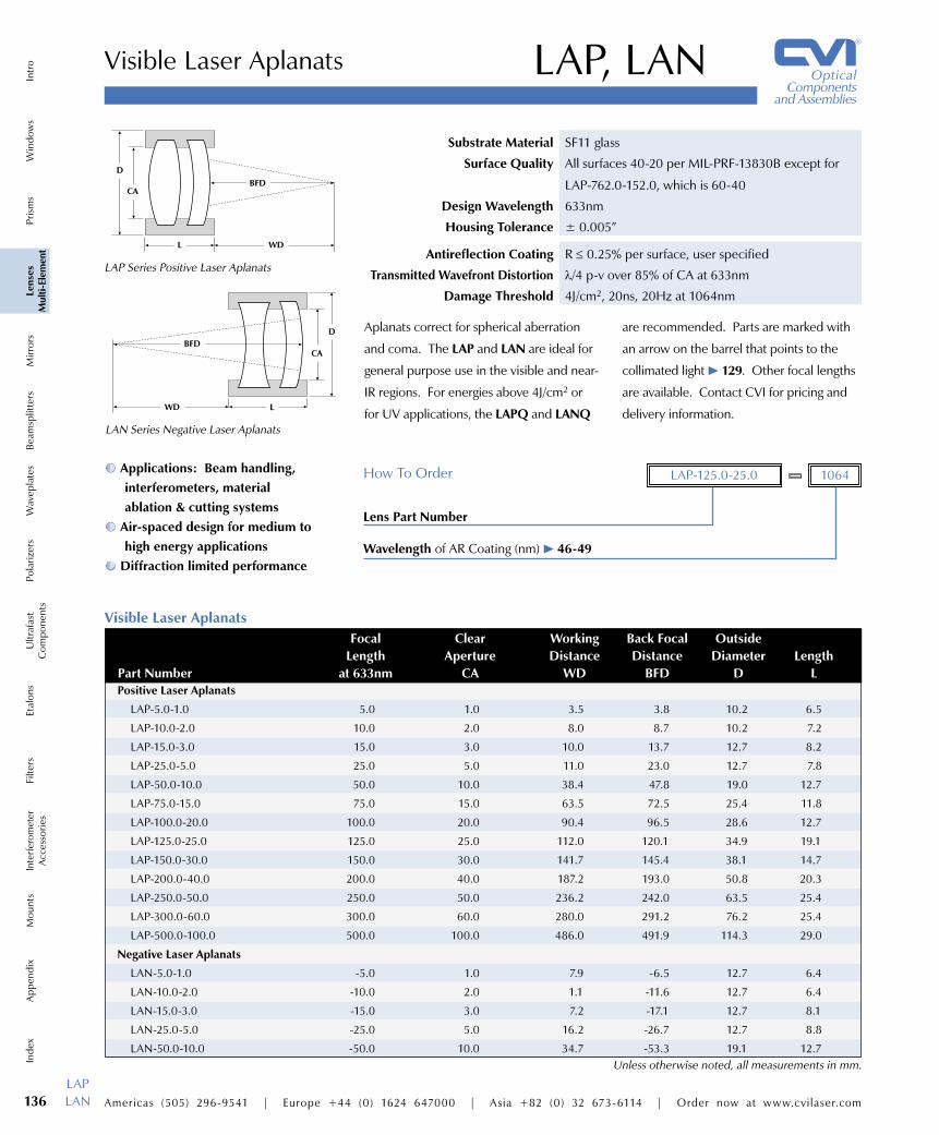
Visible Laser Aplanats
Substrate Material SF11 glass
Surface Quality All surfaces 40-20 per MIL-PRF-13830B except for
LAP-762.0-152.0, which is 60-40
Design Wavelength 633nm
Housing Tolerance ± 0.005”
LAP, LAN
Lens Part Number
Wavelength of AR Coating (nm) l 46-49
How To Order 1064LAP-125.0-25.0
LAN Series Negative Laser Aplanats
����
�� �
��
LAP Series Positive Laser Aplanats
�
�����
���
Applications: Beam handling, interferometers, material ablation & cutting systems
Air-spaced design for medium to high energy applications
Diffraction limited performance
Aplanats correct for spherical aberration
and coma. The LAP and LAN are ideal for
general purpose use in the visible and near-
IR regions. For energies above 4J/cm2 or
for UV applications, the LAPQ and LANQ
are recommended. Parts are marked with
an arrow on the barrel that points to the
collimated light l 129. Other focal lengths
are available. Contact CVI for pricing and
delivery information.
LAPLAN
Visible Laser Aplanats Focal Clear Working Back Focal Outside Length Aperture Distance Distance Diameter Length Part Number at 633nm CA WD BFD D L
Positive Laser Aplanats
LAP-5.0-1.0 5.0 1.0 3.5 3.8 10.2 6.5
LAP-10.0-2.0 10.0 2.0 8.0 8.7 10.2 7.2
LAP-15.0-3.0 15.0 3.0 10.0 13.7 12.7 8.2
LAP-25.0-5.0 25.0 5.0 11.0 23.0 12.7 7.8
LAP-50.0-10.0 50.0 10.0 38.4 47.8 19.0 12.7
LAP-75.0-15.0 75.0 15.0 63.5 72.5 25.4 11.8
LAP-100.0-20.0 100.0 20.0 90.4 96.5 28.6 12.7
LAP-125.0-25.0 125.0 25.0 112.0 120.1 34.9 19.1
LAP-150.0-30.0 150.0 30.0 141.7 145.4 38.1 14.7
LAP-200.0-40.0 200.0 40.0 187.2 193.0 50.8 20.3
LAP-250.0-50.0 250.0 50.0 236.2 242.0 63.5 25.4
LAP-300.0-60.0 300.0 60.0 280.0 291.2 76.2 25.4
LAP-500.0-100.0 500.0 100.0 486.0 491.9 114.3 29.0
Negative Laser Aplanats
LAN-5.0-1.0 -5.0 1.0 7.9 -6.5 12.7 6.4
LAN-10.0-2.0 -10.0 2.0 1.1 -11.6 12.7 6.4
LAN-15.0-3.0 -15.0 3.0 7.2 -17.1 12.7 8.1
LAN-25.0-5.0 -25.0 5.0 16.2 -26.7 12.7 8.8
LAN-50.0-10.0 -50.0 10.0 34.7 -53.3 19.1 12.7Unless otherwise noted, all measurements in mm.
Antireflection Coating R ≤ 0.25% per surface, user specified
Transmitted Wavefront Distortion λ/4 p-v over 85% of CA at 633nm
Damage Threshold 4J/cm2, 20ns, 20Hz at 1064nm
Americas (505) 296-9541 | Europe +44 (0) 1624 647000 | Asia +82 (0) 32 673-6114 | Order now at www.cvilaser.com 137
IndexInterferom
eterA
ccessoriesA
ppendixFilters
Mounts
EtalonsPolarizers
Beamsplitters
Ultrafast
Com
ponentsM
irrorsW
aveplatesLenses
Multi-Elem
entPrism
sW
indows
Intro
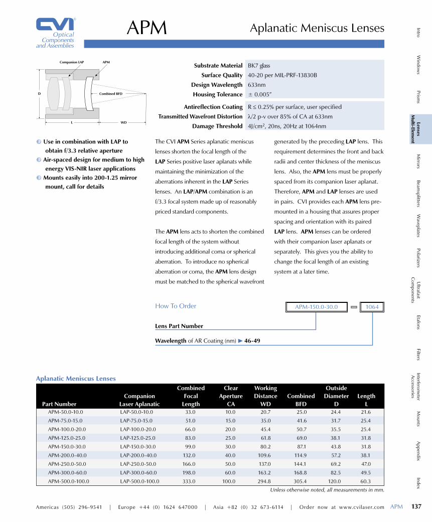
Use in combination with LAP to obtain f/3.3 relative aperture
Air-spaced design for medium to high energy VIS-NIR laser applications
Mounts easily into 200-1.25 mirror mount, call for details
APM Aplanatic Meniscus Lenses
Substrate Material BK7 glass
Surface Quality 40-20 per MIL-PRF-13830B
Design Wavelength 633nm
Housing Tolerance ± 0.005”
Lens Part Number
Wavelength of AR Coating (nm) l 46-49
How To Order 1064APM-150.0-30.0
�
���
������������
������������� ���
The CVI APM Series aplanatic meniscus
lenses shorten the focal length of the
LAP Series positive laser aplanats while
maintaining the minimization of the
aberrations inherent in the LAP Series
lenses. An LAP/APM combination is an
f/3.3 focal system made up of reasonably
priced standard components.
The APM lens acts to shorten the combined
focal length of the system without
introducing additional coma or spherical
aberration. To introduce no spherical
aberration or coma, the APM lens design
must be matched to the spherical wavefront
generated by the preceding LAP lens. This
requirement determines the front and back
radii and center thickness of the meniscus
lens. Also, the APM lens must be properly
spaced from its companion laser aplanat.
Therefore, APM and LAP lenses are used
in pairs. CVI provides each APM lens pre-
mounted in a housing that assures proper
spacing and orientation with its paired
LAP lens. APM lenses can be ordered
with their companion laser aplanats or
separately. This gives you the ability to
change the focal length of an existing
system at a later time.
Aplanatic Meniscus Lenses Combined Clear Working Outside Companion Focal Aperture Distance Combined Diameter Length Part Number Laser Aplanatic Length CA WD BFD D L
APM-50.0-10.0 LAP-50.0-10.0 33.0 10.0 20.7 25.0 24.4 21.6
APM-75.0-15.0 LAP-75.0-15.0 51.0 15.0 35.0 41.6 31.7 25.4
APM-100.0-20.0 LAP-100.0-20.0 66.0 20.0 45.4 50.7 35.5 25.4
APM-125.0-25.0 LAP-125.0-25.0 83.0 25.0 61.8 69.0 38.1 31.8
APM-150.0-30.0 LAP-150.0-30.0 99.0 30.0 80.2 87.1 43.8 31.8
APM-200.0-40.0 LAP-200.0-40.0 132.0 40.0 109.6 114.9 57.2 38.1
APM-250.0-50.0 LAP-250.0-50.0 166.0 50.0 137.0 144.1 69.2 47.0
APM-300.0-60.0 LAP-300.0-60.0 198.0 60.0 163.2 168.8 82.5 49.5
APM-500.0-100.0 LAP-500.0-100.0 333.0 100.0 294.8 305.4 120.0 60.3
Unless otherwise noted, all measurements in mm.
APM
Antireflection Coating R ≤ 0.25% per surface, user specified
Transmitted Wavefront Distortion λ/2 p-v over 85% of CA at 633nm
Damage Threshold 4J/cm2, 20ns, 20Hz at 1064nm

138 Americas (505) 296-9541 | Europe +44 (0) 1624 647000 | Asia +82 (0) 32 673-6114 | Order now at www.cvilaser.com
Win
dow
sPr
ism
sLe
nses
Mul
ti-El
emen
tM
irror
sIn
tro
Beam
split
ters
Pola
rizer
sW
avep
late
sEt
alon
sFi
lters
Ultr
afas
tC
ompo
nent
sIn
terfe
rom
eter
Acc
esso
ries
App
endi
xM
ount
sIn
dex
LANQ Negative High Energy / UV Laser Aplanats
����
�� �
��
LAPQ Positive High Energy / UV Laser Aplanats
�
�����
���
Beam handling, interferometers, material ablation & cutting systems
Air-spaced fused silica design for high energy or UV applications
Diffraction limited aplanats corrected for spherical aberration and coma
High Energy / UV Laser Aplanats
Substrate Material UV grade fused silica
Surface Quality All surfaces 10-5 CVI Laser Quality defined on page 430
Design Wavelength 248nm
Housing Tolerance ± 0.005”
LAPQ, LANQ
Lens Part Number
Wavelength of AR Coating (nm) l 46-49
248 257 266 308 325 355 1064
How To Order 248LAPQ-5.0-1.0
Also used as excimer focusing lenses,
aplanats correct for spherical aberration
and coma. Air-spaced fused silica design
provides for significantly higher energy
damage threshold performance. Parts
are marked with an arrow on the barrel
that points to the collimated light l 129.
Other focal lengths are available. Contact
CVI for pricing and delivery infromation.
LAPQLANQ
High Energy / UV Laser Aplanats Focal Focal Clear Working Back Focal Outside Length Length Aperture Distance Distance Diameter Length Part Number at 248nm at 1064nm CA WD BFD D L
Positive UV Laser Aplanats
LAPQ-5.0-1.0 5.0 5.6 1.0 3.3 3.7 10.2 6.5
LAPQ-10.0-2.0 10.0 11.4 2.0 8.7 8.8 10.2 7.2
LAPQ-15.0-3.0 15.0 17.0 3.0 14.4 15.4 12.7 8.2
LAPQ-25.0-5.0 25.0 28.3 5.0 21.7 22.7 12.7 7.8
LAPQ-50.0-10.0 50.0 56.7 10.0 46.7 47.7 19.0 12.7
LAPQ-75.0-15.0 75.0 84.9 15.0 70.0 71.1 25.4 11.8
LAPQ-100.0-20.0 100.0 113.1 20.0 95.0 96.5 28.6 12.7
LAPQ-125.0-25.0 125.0 141.3 25.0 118.0 120.1 34.9 19.1
LAPQ-150.0-30.0 150.0 169.6 30.0 142.0 145.0 38.1 14.7
LAPQ-200.0-40.0 200.0 226.1 40.0 190.0 192.2 50.8 20.3
LAPQ-250.0-50.0 250.0 282.6 50.0 228.0 230.3 63.5 25.4
LAPQ-300.0-60.0 300.0 339.2 60.0 285.0 289.9 76.2 25.4
LAPQ-500.0-100.0 500.0 565.3 100.0 480.0 485.0 114.3 29.0
Negative UV Laser Aplanats
LANQ-5.0-1.0 -5.0 -5.7 1.0 3.7 -6.4 12.7 6.4
LANQ-10.0-2.0 -10.0 -11.3 2.0 8.7 -11.4 12.7 6.4
LANQ-15.0-3.0 -15.0 -17.0 3.0 13.4 -16.6 12.7 8.1
LANQ-25.0-5.0 -25.0 -28.3 5.0 23.4 -26.6 12.7 8.8
LANQ-50.0-10.0 -50.0 -56.6 10.0 52.9 -58.9 19.1 12.7Unless otherwise noted, all measurements in mm.
Antireflection Coating R ≤ 0.25% per surface, user specified
Transmitted Wavefront Distortion λ/4 p-v over CA at 248nm
Damage Threshold 15J/cm2, 20ns, 20Hz at 1064nm

Americas (505) 296-9541 | Europe +44 (0) 1624 647000 | Asia +82 (0) 32 673-6114 | Order now at www.cvilaser.com 139
IndexInterferom
eterA
ccessoriesA
ppendixFilters
Mounts
EtalonsPolarizers
Beamsplitters
Ultrafast
Com
ponentsM
irrorsW
aveplatesLenses
Multi-Elem
entPrism
sW
indows
Intro
Use in combination with LAPQ to obtain f/3.3 relative aperture
Air-spaced design for high power and UV laser applications
Excimer focusing triplet lens Mounts easily into 200-1.25 mirror
mount, call for details
APMQ UV Aplanatic Meniscus Lenses
Substrate Material UV grade fused silica
Surface Quality 10-5 CVI Laser Quality defined on page 430
Design Wavelength 248nm
Housing Tolerance ± 0.005”�
���
������������
�������������� ����
Lens Part Number
Wavelength of AR Coating (nm) l 46-49
248 257 266 308 325 355 1064
How To Order 308APMQ-150.0-30.0
The CVI APMQ Series aplanatic meniscus
lenses shorten the focal length of the
LAPQ Series positive laser aplanats while
maintaining the minimization of the
aberrations inherent in the LAPQ Series
lenses. An LAPQ/APMQ combination is an
f/3.3 focal system made up of reasonably
priced standard components.
The APMQ lens acts to shorten the
combined focal length of the system
without introducing additional coma
or spherical aberration. To introduce
no spherical aberration or coma, the
APMQ lens design must be matched to
the spherical wavefront generated by the
preceding LAPQ lens. This requirement
determines the front and back radii and
center thickness of the meniscus lens.
Also, the APMQ lens must be properly
spaced from its companion laser aplanat.
Therefore, APMQ and LAPQ lenses are
used in pairs. CVI provides each APMQ
lens pre-mounted in a housing that assures
proper spacing and orientation with its
paired LAPQ lens. APMQ lenses can
be ordered with their companion laser
aplanats or separately. This gives you the
ability to change the focal length of an
existing system at a later time.
UV Aplanatic Meniscus Lenses Combined Clear Working Outside Companion Focal Aperture Distance Combined Diameter Length Part Number Laser Aplanatic Length CA WD BFD D L
APMQ-50.0-10.0 LAPQ-50.0-10.0 33.0 10.0 20.5 24.8 24.4 21.6
APMQ-75.0-15.0 LAPQ-75.0-15.0 49.0 15.0 31.8 40.5 31.8 25.4
APMQ-100.0-20.0 LAPQ-100.0-20.0 66.0 20.0 48.3 52.7 35.6 26.7
APMQ-125.0-20.0 LAPQ-125.0-20.0 82.0 25.0 60.9 69.0 38.1 31.8
APMQ-150.0-30.0 LAPQ-150.0-30.0 99.5 30.0 92.0 99.5 43.8 31.8
APMQ-200.0-40.0 LAPQ-200.0-40.0 129.0 40.0 105.4 113.0 57.2 38.1
APMQ-250.0-50.0 LAPQ-250.0-50.0 163.0 50.0 133.5 141.0 69.2 47.0
APMQ-300.0-60.0 LAPQ-300.0-60.0 192.0 60.0 165.5 173.0 82.5 63.0
APMQ-500.0-100.0 LAPQ-500.0-100.0 280.3 85.0 242.0 252.7 120.0 60.3
Unless otherwise noted, all measurements in mm.
APMQ
Antireflection Coating R ≤ 0.25% per surface, user specified
Transmitted Wavefront Distortion λ/2 p-v over 85% of CA at 248nm
Damage Threshold 15J/cm2, 20ns, 20Hz at 1064nm

140 Americas (505) 296-9541 | Europe +44 (0) 1624 647000 | Asia +82 (0) 32 673-6114 | Order now at www.cvilaser.com
Win
dow
sPr
ism
sLe
nses
Mul
ti-El
emen
tM
irror
sIn
tro
Beam
split
ters
Pola
rizer
sW
avep
late
sEt
alon
sFi
lters
Ultr
afas
tC
ompo
nent
sIn
terfe
rom
eter
Acc
esso
ries
App
endi
xM
ount
sIn
dex
UV and Excimer Focusing Lenses UVAP
CVI has designed this series of lenses for
focusing large diameter excimer laser
beams and for other monochromatic
ultraviolet imaging applications. They are
used in beam delivery systems for excimer
laser photoablation and also in excimer
and Raman-shifted-excimer LIDAR setups.
This series should be considered whenever
diffraction limited performance in the
ultraviolet is needed at a modest f/#.
CVI can help quantify the performance at
wavelengths other than 248nm. All but
the three fastest singlets are diffraction
limited at full clear aperture (CA) at
248nm. The criterion we use is the
wavefront error. At a peak-to-valley
wavefront error of < λ/4, more than 68%
of the focused energy is contained within
the Airy disk. This compares favorably
with diffraction limited systems where
84% of the energy appears inside the first
dark ring of the Airy pattern.
�
��
��
Outside Diameter (D) 63.5mm
Center Thickness (TC) 8.0mm
Clear Aperture (CA) 50.0mm
Singlet Specifications
�
��
�
Outside Diameter (D) 63.5mm
Length (L) 25.4mm
Clear Aperture (CA) 50.0mm
Doublet Specifications
�
��
�
Outside Diameter (D) 63.5mm
Length (L) 25.4mm
Clear Aperture (CA) 50.0mm
Triplet Specifications
Unless otherwise noted, all measurements in mm.
UV and Excimer Laser Focusing Lenses Focal Length BFD Wavefront Error Part Number Lens Type at 248nm f/D at 248nm at 248nm (λ)
PLCX-63.5-381.2-UV Singlet 750.0 15.0 744.1 0.23
PLCX-63.5-317.7-UV Singlet 625.0 12.5 619.1 0.54
PLCX-63.5-254.1-UV Singlet 500.0 10.0 493.8 1.05
PLCX-63.5-190.6-UV Singlet 375.0 7.5 368.5 2.51
UVAP-500.0-50.0 Doublet 500.0 10.0 496.8 0.05
UVAP-375.0-50.0 Doublet 375.0 7.5 370.0 0.03
UVAP-250.0-50.0 Doublet 250.0 5.0 243.9 0.19
UVAP-125.0-50.0 Triplet 125.0 2.5 108.9 0.24
Substrate Material UV grade fused silica
Surface Quality 10-5 CVI Laser Quality defined on page 430
Focal Length Tolerance ± 0.5%
Clear Aperture 50.0mm
Housing Tolerance ± 0.005”
Beam handling, interferometers, material ablation & cutting systems
Air-spaced fused silica design for high energy or UV applications
All CVI AR coating available l 46-49 Use the 33-UVAP lens mount
holder l 396
UVAP
Lens Part Number
Wavelength of AR Coating (nm) l 46-49
193-248 248-355 266 325 1064
248 257 308 355
How To Order 325UVAP-375.0-50.0
Transmitted Wavefront Distortion see table below
Damage Threshold 1J/cm2, 20ns, 20Hz at 248nm

Americas (505) 296-9541 | Europe +44 (0) 1624 647000 | Asia +82 (0) 32 673-6114 | Order now at www.cvilaser.com 141
IndexInterferom
eterA
ccessoriesA
ppendixFilters
Mounts
EtalonsPolarizers
Beamsplitters
Ultrafast
Com
ponentsM
irrorsW
aveplatesLenses
Multi-Elem
entPrism
sW
indows
Intro
Perfect for micromachining, laser scribing, and microlithography
Air-Spaced Doublet or Triplet design for maximum UV transmission
Infinite conjugate ratio design
����������������������������
��������������
������������������
������������
������������������
����������������������������������������������
���������
Substrate Material UV grade fused silica
Design Wavelength 355nm
Housing Black anodized barrel or mounted into a microscope
objective style stainless steel housing
UVO UV Objective Lenses
Product Code
Focal Length in mm
Clear Aperture Diameter in mm
Wavelength Range of AR Coating in nm
193-248 248-355 355-532
How To Order 248-3553.014.0UVO
High damage threshold makes this ideal
for micromachining applications. We offer
these lenses in a black anodized aluminum
barrel alone or in the convenience of a
microscope objective style housing. The
housing has standard Royal Microscope
Society screw threads [0.8” x 36TPI].
For higher damage threshold, it is
recommended to use a narrowband
antireflection coating (V-coat). Call CVI
for pricing and delivery.
UVO
UV Objective Lenses Focal Magnification BBAR Part Number Length f/# NA (170mm/fl) BFD WD CA Coating (nm)
UVO-4.0-0.75-193-248 4.0 5.3 0.09 42.50 2.01 1.63 0.75 193-248
UVO-10.3-3.2-193-248 10.3 3.2 0.15 16.50 6.30 5.85 3.20 193-248
UVO-14.0-3.0-193-248 14.0 4.7 0.11 12.10 7.80 6.50 3.00 193-248
UVO-20.0-10.0-193-248 20.0 2.1 0.23 7.96 14.80 13.00 10.00 193-248
UVO-4.0-0.75-248-355 4.0 5.3 0.09 42.50 2.00 1.63 0.75 248-355
UVO-10.3-3.2-248-355 10.3 3.2 0.15 16.50 6.30 5.90 3.20 248-355
UVO-14.0-3.0-248-355 14.0 4.7 0.11 12.10 7.80 6.50 3.00 248-355
UVO-20.0-10.0-248-355 20.0 2.1 0.23 7.96 14.80 13.00 10.00 248-355
UVO-4.0-0.75-355-532 4.0 5.3 0.09 42.50 2.00 1.63 0.75 355-532
UVO-10.3-3.2-355-532 10.3 3.2 0.15 16.50 6.30 5.85 3.20 355-532
UVO-14.0-3.0-355-532 14.0 4.7 0.11 12.10 7.80 6.50 3.00 355-532
UVO-20.0-10.0-355-532 20.0 2.1 0.23 7.96 14.80 13.00 10.00 355-532Unless otherwise noted, all measurements in mm.
Antireflection Coating User specified, Ravg ≤ 0.5% per surface
Transmitted Wavefront Distortion 3/4 λ p-v at 633nm
Damage Threshold 500mJ/cm2, 20ns, 20Hz at 355nm

142 Americas (505) 296-9541 | Europe +44 (0) 1624 647000 | Asia +82 (0) 32 673-6114 | Order now at www.cvilaser.com
Win
dow
sPr
ism
sLe
nses
Mul
ti-El
emen
tM
irror
sIn
tro
Beam
split
ters
Pola
rizer
sW
avep
late
sEt
alon
sFi
lters
Ultr
afas
tC
ompo
nent
sIn
terfe
rom
eter
Acc
esso
ries
App
endi
xM
ount
sIn
dex
FTLF-Theta Lenses
Provides a flat field at the image plane of the scan
Image velocity is proportional to the angular velocity of the scanning mirror
Substrate Material SF11 and BK7 glass
Design Wavelength 1064nm
��
���
���
��������
��
EFL Effective Focal Length
BFL Back Focal Length
SL Scan Length
BD Beam Diameter
θ Scan Angle (±)
IPS Image Point Size (µm)
D Overall Diameter
F-Theta lenses are commonly used in
conjunction with galvonometer scanning
mirrors in laser marking, engraving, and
cutting systems along with Nd:YAG or
Fiber Laser Sources. F-Theta lenses provide
a flat image field at the plane of interest.
CVI designs have been developed for
common wavelengths and focal lengths.
Standard features include air-spaced design
FTL
for high damage threshold, anti-reflection
coatings on all surfaces, and M85x1 screw
thread for easy fixturing.
In addition to the lenses shown below,
CVI designs custom lenses for other OEM
applications, specifications levels or price
ranges. Please contact a CVI application
engineer for further information.
Antireflection Coating R < 0.5% per surface
Transmitted Wavefront Distortion λ/4 p-v at 633nm per MIL-PRF-13830B
Clear Aperture 90%
Damage Threshold 1J/cm2, 8nsec pulse; 1MW/cm2, CW at 1064nm
Unless otherwise noted, all measurements in mm.
F-Theta Lenses Back Scan Entrance Image Effective Focal Length Beam Scan Point Mirror Assembly Focal Length Size Diameter Angle ° (±) Size (µm) Distance Diameter Part Number Wavelength Length (BFL) (SL) (BD) θ (IPS) (a1/a2) (D)
FTL-1064-160 1064nm 160.0 189.1 159.0 10.0 28.5° 23µm 38/25 110.0
FTL-1064-163 1064nm 163.0 190.0 162.0 10.0 28.5° 26µm 38/25 109.0
FTL-1064-254 1064nm 254.0 300.5 260.2 20.0 29.3° 20µm 39.5/19.5 126.0